Hydraulic Flow Rectifier Circuit
Warning: This example uses the hydraulic domain, which will be removed in a future release. Find an equivalent example model that uses the isothermal liquid domain here: Hydraulic Flow Rectifier Circuit. To convert models to the isothermal liquid domain, use the hydraulicToIsothermalLiquid tool.
This example shows a flow rectifier circuit, which consists of four check valves and a flow control valve. It is used to control flow rate flowing in both directions with only one flow control valve. Similar to a Graetz circuit implemented with diodes, the check valves are arranged in such a way that flow always passes through the flow control valve in the same direction. Two other check valves, Flow BA Check Valve and Flow AB Check Valve, are used to select an orifice depending on the flow direction.
For more information on an electrical Graetz circuit implementation, see Full-Wave Bridge Rectifier.
Model

Simulation Results from Simscape Logging
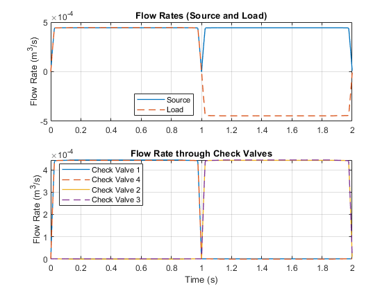
The plots below show the flow rate through various components in the system. Though the flow rate from the source (controlled by the 4-Way Valve) changes direction, the flow rate in the load (Flow Control Valve) remains in the same direction. The flow rates through the check valves are plotted to show how the flow proceeds through the flow rectifier.