DAC DC Measurement
Measure DC performance metrics of DAC output
Libraries:
Mixed-Signal Blockset /
DAC /
Measurements & Testbenches
Description
The DAC DC Measurement block measures DAC DC performance metrics such as offset error, gain error, integral nonlinearity (INL), and differential nonlinearity (DNL) errors. You can use the DAC DC Measurement block to validate the DAC architecture models provided in Mixed-Signal Blockset™, or you can use a DAC of your own implementation.
Examples
This example shows how to find DC performance metrics such as offset error, gain error, INL, and DNL.
Open the model dac_dc_measure
. The model consists of a Signal Generator, a Flash ADC, a Binary Weighted DAC block, and a DAC AC Measurement block.
model = 'dac_dc_measure';
open_system(model)
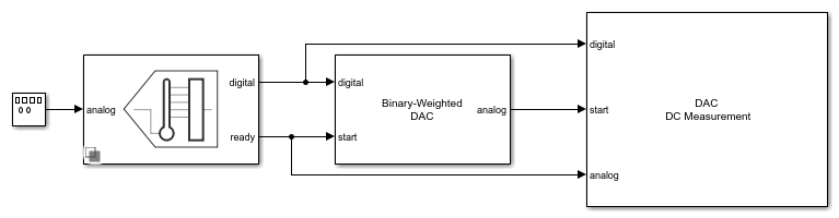
The Flash ADC acts as the input to the Binary Weighted DAC. The ADC uses an internal start clock whose Conversion start frequency (Hz) is 1e6
and RMS aperture jitter (s) is 1e-12
. The input analog frequency to the Flash ADC from the Signal generator is 900
Hz.
The Number of bits of the Binary Weighted DAC is set to 10
. The impairments are enabled in the Impairments tab, and the value of the offset error and gain error are set to 2
LSB and 1
LSB, respectively. All other parameters are kept at their default values.
The Number of bits and Conversion start frequency (Hz) of the DAC DC Measurement block are 10
and 1e6
, respectively. The Settling time (s) of the DAC DC Measurement block is set to 4e-7
, twice the Settling time (s) of the Binary Weighted DAC to ensure the entire transition period is not considered as part of the steady-state DC measurements.
Run the simulation for 0.02558
s. The measured AC performance metrics are displayed on the DAC AC Measurement block.
Ports
Input
Digital signal from a DAC, specified as a scalar.
Data Types: fixed point
| single
| double
| int8
| int16
| int32
| uint8
| uint16
| uint32
Converted analog signal from a DAC, specified as a scalar.
Data Types: double
External clock to start conversion, specified as a scalar. This port determines when digital-to-analog conversion process starts.
Data Types: double
Parameters
Polarity of the input signal to the DAC.
Programmatic Use
Block parameter:
Polarity |
Type: character vector |
Values:
Bipolar |Unipolar |
Default:
Bipolar |
Reference voltage of the DAC, specified as a real scalar in volts. Reference (V) helps determine the output from the input digital code, Number of bits, and Bias (V) using the equation:
.
Programmatic Use
Block parameter:
Ref |
Type: character vector |
Values: real scalar |
Default:
2 |
Data Types: double
Bias voltage added to the output of the DAC, specified as a real scalar in volts. Bias (V) helps determine the output from the input digital code, Number of bits, and Reference (V) using the equation:
.
Programmatic Use
Block parameter:
Bias |
Type: character vector |
Values: real scalar |
Default:
0 |
Data Types: double
The time required for the output of the DAC to settle to within some fraction of its final value, specified as a nonnegative real scalar in seconds.
Programmatic Use
Block parameter:
SettlingTime |
Type: character vector |
Values: real scalar |
Default:
3e-7 |
Data Types: double
Delay before measurement analysis to avoid corruption by transients, specified as a nonnegative real scalar in seconds.
Programmatic Use
Block parameter:
HoldOffTime |
Type: character vector |
Values: nonnegative real scalar |
Default:
1e-3 |
Data Types: double
Number of bits in the input word, specified as a unitless positive real integer. Number of bits determines the resolution of the DAC.
Programmatic Use
Block parameter:
NBits |
Type: character vector |
Values: positive real integer |
Default:
10 |
Data Types: double
Frequency of the internal start conversion clock, specified as a real scalar in Hz. The Start conversion frequency parameter determines the conversion rate at the start of conversion.
Programmatic Use
Block parameter:
StartFreq |
Type: character vector |
Values: positive real scalar |
Default:
1e6 |
Data Types: double
Minimum time the simulation must run to obtain meaningful results, specified as a positive real scalar in seconds.
To measure DC performance, the simulation must run so that the DAC can sample each digital code 20 times. Based on this assumption, the Recommended simulation stop time (s) T is given by:
,
where StartFreq is the frequency of the conversion start clock and Nbits is the resolution of the DAC.
The number of samples per bit is calculated using the equation:
.
This parameter is only reported by the block and is not editable.
Data Types: double
Measure the differential nonlinearity (DNL) error and integral nonlinearity (INL) error using the endpoint method. This method uses the endpoints of the actual transfer function to measure the DNL and INL errors.
Measure the differential nonlinearity (DNL) error and integral nonlinearity (INL) error using the best fit method. This method uses a standard curve-fitting technique to find the best fit to measure the DNL and INL errors.
Select to store detailed test results to a struct
in the base
workspace for further processing at the end of simulation. By default, this parameter is
deselected.
Name of the variable that stores detailed test results, specified as a character string.
Dependencies
To enable this parameter, select Output result to base workspace parameter.
Programmatic Use
Block parameter:
VariableName |
Type: character vector |
Values: character string |
Default:
dac_dc_out |
Click to plot measurement result for further analysis.
More About
Offset error represents the offset of the DAC transfer function curve from it ideal value at a single point.
Gain error represents the deviation of the slope of the DAC transfer function curve from its ideal value.
Integral nonlinearity (INL) error, also termed as relative accuracy, is the maximum deviation of the measured transfer function from a straight line. The straight line can either be a best fit using standard-curve fitting technique, or be drawn between the endpoints of the actual transfer function after gain adjustment.
The best fit method gives a better prediction of distortion in AC applications, and a lower value of linearity error. The endpoint method is mostly used in the measurement applications of data converters, since the error budget depends on actual deviation from the ideal transfer function.
Differential nonlinearity (DNL) is the deviation from the ideal difference (1 LSB) between analog input levels that trigger any two successive digital output levels. The DNL error is the maximum value of DNL found at any transition.
Version History
Introduced in R2020a
See Also
MATLAB Command
You clicked a link that corresponds to this MATLAB command:
Run the command by entering it in the MATLAB Command Window. Web browsers do not support MATLAB commands.
Select a Web Site
Choose a web site to get translated content where available and see local events and offers. Based on your location, we recommend that you select: .
You can also select a web site from the following list
How to Get Best Site Performance
Select the China site (in Chinese or English) for best site performance. Other MathWorks country sites are not optimized for visits from your location.
Americas
- América Latina (Español)
- Canada (English)
- United States (English)
Europe
- Belgium (English)
- Denmark (English)
- Deutschland (Deutsch)
- España (Español)
- Finland (English)
- France (Français)
- Ireland (English)
- Italia (Italiano)
- Luxembourg (English)
- Netherlands (English)
- Norway (English)
- Österreich (Deutsch)
- Portugal (English)
- Sweden (English)
- Switzerland
- United Kingdom (English)