Main Content

Constant Gamma Clutter

Constant gamma clutter simulation

Since R2021a

  • Constant Gamma Clutter block

Libraries:
Radar Toolbox

Description

The Constant Gamma Clutter block generates constant gamma clutter reflected from homogeneous terrain for a monostatic radar transmitting a narrowband signal into free space. The radar is assumed to be at constant altitude moving at constant speed.

Ports

Input

expand all

Index to select the pulse repetition frequency (PRF), specified as a positive integer. The index selects the PRF from the predefined vector of values specified by the Pulse repetition frequency (Hz) parameter.

Example: 4

Dependencies

To enable this port, select Enable PRF selection input.

Data Types: double

Weights applied to each element in array, specified as a length-N complex-valued vector. N is the number of elements in the array selected in the Sensor array panel.

Dependencies

To enable this port, select the Enable weights input check box.

Data Types: double
Complex Number Support: Yes

Weights applied to each element in a subarray, specified as an NE-by-NS complex-valued matrix.

  • When you set Specify sensor array to Replicated Subarray, all subarrays have the same dimensions. Then, you can specify the subarray element weights as a complex-valued NE-by-NS matrix. NE is the number of elements in each subarray and NS is the number of subarrays. Each column of WS specifies the weights for the corresponding subarray.

  • When you set Specify sensor array to Partitioned array, subarrays are not required to have identical dimensions and sizes. You can specify subarray element weights as a complex-valued NE-by-NS matrix, where NE now is the number of elements in the largest subarray. The first K entries in each column are the element weights for the corresponding subarray where K is the number of elements in the subarray.

Dependencies

To enable this port, set Specify sensor array to Partitioned array or Replicated Subarray. Then, set Subarray steering method to Custom.

Data Types: double
Complex Number Support: Yes

Steering angle, specified as a scalar or a 2-by-1 real-valued vector. As a vector, the steering angle takes the form of [AzimuthAngle; ElevationAngle]. As a scalar, the steering angle represents the azimuth angle only. Then the elevation angle is assumed to be zero degrees. Units are in degrees

Dependencies

To enable this port, set Specify sensor array to Partitioned array or Replicated Subarray. Then, set Subarray steering method to Phase or Time.

Data Types: double

Output

expand all

Simulated clutter, returned as an N-by-M complex-valued matrix.

N is the number of samples output from the block. When you set the Output signal format parameter to Samples, specify N using the Number of samples in output parameter. When you set the Output signal format parameter to Pulses, N is the total number of samples in the next P pulses where P is specified in the Number of pulse in output parameter.

M is either

  • the number of subarrays in the sensor array if sensor array contains subarrays.

  • the number of radiating or collecting elements if the sensor array does not contain subarrays.

Data Types: double

Parameters

expand all

Main Tab

Clutter model parameter, specified as a scalar. This parameter contains the γ value used in the constant γ clutter model. The γ value depends on both terrain type and the operating frequency. Units are in dB.

Example: -5.0

Data Types: double

Specify the earth model used in clutter simulation as Flat or Curved. When you set this parameter to Flat, the earth is assumed to be a plane. When you set this parameter to Curved, the earth is assumed to be spherical.

Specify the minimum range for the clutter simulation as a positive scalar. The minimum range must be nonnegative. Units are in meters.

Specify the maximum range for the clutter simulation as a positive scalar. The maximum range must be greater than the value specified in the Radar height parameter. Units are in meters.

The azimuth angle in the ground plane about which clutter patches are generated. Patches are generated symmetrically about this angle. Units are in degrees.

Specify the azimuth span of each clutter patch as a positive scalar. Units are in degrees. Units are in degrees.

Azimuth span of each clutter patch, specified as a positive scalar. Units are in degrees.

Data Types: double

Coherence time for the clutter simulation, specified as a positive scalar. After the coherence time elapses, the block updates the random numbers it uses for the clutter simulation at the next pulse. When you use the default value of Inf, the random numbers are never updated. Units are in seconds.

Example: 4

Data Types: double

Signal propagation speed, specified as a real-valued positive scalar. The default value of the speed of light is the value returned by physconst('LightSpeed'). Units are in meters per second.

Example: 3e8

Data Types: double

Clutter sample rate, specified as a positive scalar. Units are in Hertz.

Example: 10e6

Data Types: double

Pulse repetition frequency, PRF, specified as a positive scalar or a row vector of positive values. Units are in Hertz.

Example: [1e4,2e4]

Data Types: double

Select this parameter to enable the PRFIdx port.

  • When enabled, pass in an index into a vector of predefined PRFs. Set predefined PRFs using the Pulse repetition frequency (Hz) parameter.

  • When not enabled, the block cycles through the vector of PRFs specified by the Pulse repetition frequency (Hz) parameter. If Pulse repetition frequency (Hz) is a scalar, the PRF is constant.

Source of simulation sample time, specified as Derive from waveform parameters or Inherit from Simulink engine. When set to Derive from waveform parameters, the block runs at a variable rate determined by the PRF of the selected waveform. The elapsed time is variable. When set to Inherit from Simulink engine, the block runs at a fixed rate so the elapsed time is a constant.

Dependencies

To enable this parameter, select the Enable PRF selection input parameter.

The format of the output signal, specified as Pulses or Samples.

If you set this parameter to Samples, the output of the block consists of multiple samples. The number of samples is the value of the Number of samples in output parameter.

If you set this parameter to Pulses, the output of the block consists of multiple pulses. The number of pulses is the value of the Number of pulses in output parameter.

Number of samples in the block output, specified as a positive integer.

Example: 1000

Dependencies

To enable this parameter, set the Output signal format parameter to Samples.

Data Types: double

Number of pulses in the block output, specified as a positive integer.

Example: 2

Dependencies

To enable this parameter, set the Output signal format parameter to Pulses.

Data Types: double

Block simulation, specified as Interpreted Execution or Code Generation. If you want your block to use the MATLAB® interpreter, choose Interpreted Execution. If you want your block to run as compiled code, choose Code Generation. Compiled code requires time to compile but usually runs faster.

Interpreted execution is useful when you are developing and tuning a model. The block runs the underlying System object™ in MATLAB. You can change and execute your model quickly. When you are satisfied with your results, you can then run the block using Code Generation. Long simulations run faster with generated code than in interpreted execution. You can run repeated executions without recompiling, but if you change any block parameters, then the block automatically recompiles before execution.

This table shows how the Simulate using parameter affects the overall simulation behavior.

When the Simulink® model is in Accelerator mode, the block mode specified using Simulate using overrides the simulation mode.

Acceleration Modes

Block SimulationSimulation Behavior
NormalAcceleratorRapid Accelerator
Interpreted ExecutionThe block executes using the MATLAB interpreter.The block executes using the MATLAB interpreter.Creates a standalone executable from the model.
Code GenerationThe block is compiled.All blocks in the model are compiled.

For more information, see Choosing a Simulation Mode (Simulink).

Radar Tab

System operating frequency, specified as a positive scalar. Units are in Hz.

Effective radiated power (ERP) of the radar system, specified as a positive scalar. Units are in watts.

Example: 3500

Data Types: double

Height of radar above surface, specified as a nonnegative scalar. Units are in meters.

Example: 50

Data Types: double

Radar platform speed, specified as a nonnegative scalar. Units are in meters per second.

Example: 5

Data Types: double

Specify the direction of radar platform motion as a 2-by-1 real vector in the form [AzimuthAngle;ElevationAngle]. Units are in degrees. Both azimuth and elevation angle are measured in the local coordinate system of the radar antenna or antenna array. Azimuth angle must be between –180° and 180°. Elevation angle must be between –90° and 90°.

The default value of this parameter indicates that the radar platform is moving perpendicular to the radar antenna array broadside direction.

Example: [25;30]

Data Types: double

Specify a 3-element vector that gives the intrinsic yaw, pitch, and roll of the sensor frame from the inertial frame. The 3 elements define the rotations around the z, y, and x axes respectively, in that order. The first rotation, rotates the body axes around the z-axis. Because these angles define intrinsic rotations, the second rotation is performed around the y-axis in its new position resulting from the previous rotation. The final rotation around the x-axis is performed around the x-axis as rotated by the first two rotations in the intrinsic system.

Example: [0,-10,4]

Data Types: double

Check box to enable antenna element weights input port, W.

Sensor Array Tab

Method to specify array, specified as Array (no subarrays) or MATLAB expression.

  • Array (no subarrays) — use the block parameters to specify the array.

  • Partitioned array — use the block parameters to specify the array.

  • Replicated subarray — use the block parameters to specify the array.

  • MATLAB expression — create the array using a MATLAB expression.

MATLAB expression used to create an array, specified as a valid Phased Array System Toolbox array System object.

Example: phased.URA('Size',[5,3])

Dependencies

To enable this parameter, set Specify sensor array as to MATLAB expression.

Element Parameters

Antenna or microphone type, specified as one of the following:

  • Isotropic Antenna

  • Cosine Antenna

  • Custom Antenna

  • Omni Microphone

  • Custom Microphone

Specify the operating frequency range of the antenna or microphone element as a 1-by-2 row vector in the form [LowerBound,UpperBound]. The element has no response outside this frequency range. Frequency units are in Hz.

Dependencies

To enable this parameter, set Element type to Isotropic Antenna, Cosine Antenna, or Omni Microphone.

Specify the frequencies at which to set antenna and microphone frequency responses as a 1-by-L row vector of increasing real values. The antenna or microphone element has no response outside the frequency range specified by the minimum and maximum elements of this vector. Frequency units are in Hz.

Dependencies

To enable this parameter, set Element type to Custom Antenna or Custom Microphone. Use Frequency responses (dB) to set the responses at these frequencies.

Select this check box to baffle the back response of the element. When back baffled, the responses at all azimuth angles beyond ±90° from broadside are set to zero. The broadside direction is defined as 0° azimuth angle and 0° elevation angle.

Dependencies

To enable this check box, set Element type to Isotropic Antenna or Omni Microphone.

Specify the exponents of the cosine pattern as a nonnegative scalar or a real-valued 1-by-2 matrix of nonnegative values. When Exponent of cosine pattern is a 1-by-2 vector, the first element is the exponent in the azimuth direction and the second element is the exponent in the elevation direction. When you set this parameter to a scalar, both the azimuth direction and elevation direction cosine patterns are raised to the same power.

Dependencies

To enable this parameter, set Element type to Cosine Antenna.

Frequency response of a custom antenna or custom microphone for the frequencies defined by the Operating frequency vector (Hz) parameter. The dimensions of Frequency responses (dB) must match the dimensions of the vector specified by the Operating frequency vector (Hz) parameter.

Dependencies

To enable this parameter, set Element type to Custom Antenna or Custom Microphone.

Coordinate system of custom antenna pattern, specified az-el or phi-theta. When you specify az-el, use the Azimuth angles (deg) and Elevations angles (deg) parameters to specify the coordinates of the pattern points. When you specify phi-theta, use the Phi angles (deg) and Theta angles (deg) parameters to specify the coordinates of the pattern points.

Dependencies

To enable this parameter, set Element type to Custom Antenna.

Specify the azimuth angles at which to calculate the antenna radiation pattern as a 1-by-P row vector. P must be greater than 2. Azimuth angles must lie between –180° and 180°, inclusive, and be in strictly increasing order.

Dependencies

To enable this parameter, set the Element type parameter to Custom Antenna and the Input Pattern Coordinate System parameter to az-el.

Specify the elevation angles at which to compute the radiation pattern as a 1-by-Q vector. Q must be greater than 2. Angle units are in degrees. Elevation angles must lie between –90° and 90°, inclusive, and be in strictly increasing order.

Dependencies

To enable this parameter, set the Element type parameter to Custom Antenna and the Input Pattern Coordinate System parameter to az-el.

Phi angles of points at which to specify the antenna radiation pattern, specify as a real-valued 1-by-P row vector. P must be greater than 2. Angle units are in degrees. Phi angles must lie between 0° and 360° and be in strictly increasing order.

Dependencies

To enable this parameter, set the Element type parameter to Custom Antenna and the Input Pattern Coordinate System parameter to phi-theta.

Theta angles of points at which to specify the antenna radiation pattern, specify as a real-valued 1-by-Q row vector. Q must be greater than 2. Angle units are in degrees. Theta angles must lie between 0° and 360° and be in strictly increasing order.

Dependencies

To enable this parameter, set the Element type parameter to Custom Antenna and the Input Pattern Coordinate System parameter to phi-theta.

Magnitude of the combined antenna radiation pattern, specified as a Q-by-P matrix or a Q-by-P-by-L array.

  • When the Input Pattern Coordinate System parameter is set to az-el, Q equals the length of the vector specified by the Elevation angles (deg) parameter and P equals the length of the vector specified by the Azimuth angles (deg) parameter.

  • When the Input Pattern Coordinate System parameter is set to phi-theta, Q equals the length of the vector specified by the Theta Angles (deg) parameter and P equals the length of the vector specified by the Phi Angles (deg) parameter.

The quantity L equals the length of the Operating frequency vector (Hz).

  • If this parameter is a Q-by-P matrix, the same pattern is applied to all frequencies specified in the Operating frequency vector (Hz) parameter.

  • If the value is a Q-by-P-by-L array, each Q-by-P page of the array specifies a pattern for the corresponding frequency specified in the Operating frequency vector (Hz) parameter.

Dependencies

To enable this parameter, set Element type to Custom Antenna.

Phase of the combined antenna radiation pattern, specified as a Q-by-P matrix or a Q-by-P-by-L array.

  • When the Input Pattern Coordinate System parameter is set to az-el, Q equals the length of the vector specified by the Elevation angles (deg) parameter and P equals the length of the vector specified by the Azimuth angles (deg) parameter.

  • When the Input Pattern Coordinate System parameter is set to phi-theta, Q equals the length of the vector specified by the Theta Angles (deg) parameter and P equals the length of the vector specified by the Phi Angles (deg) parameter.

The quantity L equals the length of the Operating frequency vector (Hz).

  • If this parameter is a Q-by-P matrix, the same pattern is applied to all frequencies specified in the Operating frequency vector (Hz) parameter.

  • If the value is a Q-by-P-by-L array, each Q-by-P page of the array specifies a pattern for the corresponding frequency specified in the Operating frequency vector (

Dependencies

To enable this parameter, set Element type to Custom Antenna.

Select this check box to rotate the antenna element pattern to align with the array normal. When not selected, the element pattern is not rotated.

When the antenna is used in an antenna array and the Input Pattern Coordinate System parameter is az-el, selecting this check box rotates the pattern so that the x-axis of the element coordinate system points along the array normal. Not selecting uses the element pattern without the rotation.

When the antenna is used in an antenna array and Input Pattern Coordinate System is set to phi-theta, selecting this check box rotates the pattern so that the z-axis of the element coordinate system points along the array normal.

Use the parameter in conjunction with the Array normal parameter of the URA and UCA arrays.

Dependencies

To enable this parameter, set Element type to Custom Antenna.

Polar pattern microphone response frequencies, specified as a real scalar, or a real-valued, 1-by-L vector. The response frequencies lie within the frequency range specified by the Operating frequency vector (Hz) vector.

Dependencies

To enable this parameter, set Element type set to Custom Microphone.

Specify the polar pattern response angles, as a 1-by-P vector. The angles are measured from the central pickup axis of the microphone and must be between –180° and 180°, inclusive.

Dependencies

To enable this parameter, set Element type to Custom Microphone.

Specify the magnitude of the custom microphone element polar patterns as an L-by-P matrix. L is the number of frequencies specified in Polar pattern frequencies (Hz). P is the number of angles specified in Polar pattern angles (deg). Each row of the matrix represents the magnitude of the polar pattern measured at the corresponding frequency specified in Polar pattern frequencies (Hz) and all angles specified in Polar pattern angles (deg). The pattern is measured in the azimuth plane. In the azimuth plane, the elevation angle is 0° and the central pickup axis is 0° degrees azimuth and 0° degrees elevation. The polar pattern is symmetric around the central axis. You can construct the microphone response pattern in 3-D space from the polar pattern.

Dependencies

To enable this parameter, set Element type to Custom Microphone.

Array Parameters

Array geometry, specified as one of

  • ULA — Uniform linear array

  • URA — Uniform rectangular array

  • UCA — Uniform circular array

  • Conformal Array — arbitrary element positions

The number of array elements for ULA or UCA arrays, specified as an integer greater than or equal to 2.

When you set Specify sensor array as to Replicated subarray, this parameter applies to each subarray.

Dependencies

To enable this parameter, set Geometry to ULA or UCA.

Spacing between adjacent array elements:

  • ULA — specify the spacing between two adjacent elements in the array as a positive scalar.

  • URA — specify the spacing as a positive scalar or a 1-by-2 vector of positive values. If Element spacing (m) is a scalar, the row and column spacings are equal. If Element spacing (m) is a vector, the vector has the form [SpacingBetweenArrayRows,SpacingBetweenArrayColumns].

  • When you set Specify sensor array as to Replicated subarray, this parameter applies to each subarray.

Dependencies

To enable this parameter, set Geometry to ULA or URA.

Linear axis direction of ULA, specified as y, x, or z. All ULA array elements are uniformly spaced along this axis in the local array coordinate system.

Dependencies

  • To enable this parameter, set Geometry to ULA.

  • This parameter is also enabled when the block only supports ULA arrays.

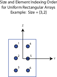
Dimensions of a URA array, specified as a positive integer or 1-by-2 vector of positive integers.

  • If Array size is a 1-by-2 vector, the vector has the form [NumberOfArrayRows,NumberOfArrayColumns].

  • If Array size is an integer, the array has the same number of rows and columns.

  • When you set Specify sensor array as to Replicated subarray, this parameter applies to each subarray.

For a URA, array elements are indexed from top to bottom along the leftmost column, and then continue to the next columns from left to right. In this figure, the Array size value of [3,2] creates an array having three rows and two columns.

Dependencies

To enable this parameter, set Geometry to URA.

Lattice of URA element positions, specified as Rectangular or Triangular.

  • Rectangular — Aligns all the elements in row and column directions.

  • Triangular — Shifts the even-row elements of a rectangular lattice toward the positive row-axis direction. The displacement is one-half the element spacing along the row dimension.

Dependencies

To enable this parameter, set Geometry to URA.

Array normal direction, specified as x, y, or z.

Elements of planar arrays lie in a plane orthogonal to the selected array normal direction. Element boresight directions point along the array normal direction.

Array Normal Parameter ValueElement Positions and Boresight Directions
xArray elements lie in the yz-plane. All element boresight vectors point along the x-axis.
yArray elements lie in the zx-plane. All element boresight vectors point along the y-axis.
zArray elements lie in the xy-plane. All element boresight vectors point along the z-axis.

Dependencies

To enable this parameter, set Geometry to URA or UCA.

Radius of UCA array, specified as a positive scalar.

Dependencies

To enable this parameter, set Geometry to UCA.

Positions of the elements in a conformal array, specified as a 3-by-N matrix of real values, where N is the number of elements in the conformal array. Each column of this matrix represents the position [x;y;z]of an array element in the array local coordinate system. The origin of the local coordinate system is (0,0,0). Units are in meters.

When you set Specify sensor array as to Replicated subarray, this parameter applies to each subarray.

Dependencies

To enable this parameter set Geometry to Conformal Array.

Direction of element normal vectors in a conformal array, specified as a 2-by-1 column vector or a 2-by-N matrix. N indicates the number of elements in the array. For a matrix, each column specifies the normal direction of the corresponding element in the form [azimuth;elevation] with respect to the local coordinate system. The local coordinate system aligns the positive x-axis with the direction normal to the conformal array. If the parameter value is a 2-by-1 column vector, the same pointing direction is used for all array elements.

When you set Specify sensor array as to Replicated subarray, this parameter applies to each subarray.

You can use the Element positions (m) and Element normals (deg) parameters to represent any arrangement in which pairs of elements differ by certain transformations. The transformations can combine translation, azimuth rotation, and elevation rotation. However, you cannot use transformations that require rotation about the normal direction.

Dependencies

To enable this parameter, set Geometry to Conformal Array.

Element tapering, specified as a complex-valued scalar or a complex-valued 1-by-N row vector. In this vector, N represents the number of elements in the array.

Also known as element weights, tapers multiply the array element responses. Tapers modify both amplitude and phase of the response to reduce side lobes or steer the main response axis.

If Taper is a scalar, the same weight is applied to each element. If Taper is a vector, a weight from the vector is applied to the corresponding sensor element. The number of weights must match the number of elements of the array.

When you set Specify sensor array as to Replicated subarray, this parameter applies to each subarray.

Specify the subarray selection as an M-by-N matrix. M is the number of subarrays and N is the total number of elements in the array. Each row of the matrix represents a subarray and each entry in the row indicates when an element belongs to the subarray. When the entry is zero, the element does not belong the subarray. A nonzero entry represents a complex-valued weight applied to the corresponding element. Each row must contain at least one nonzero entry.

The phase center of each subarray lies at the subarray geometric center. The subarray geometric center depends on the Subarray definition matrix and Geometry parameters.

Dependencies

To enable this parameter, set Specify sensor array as to Partitioned array.

Subarray steering method, specified as one of

  • None

  • Phase

  • Time

  • Custom

Selecting Phase or Time opens the Steer input port on the Narrowband Receive Array, Narrowband Transmit Array, Wideband Receive Array, Wideband Transmit Array blocks, Constant Gamma Clutter, and GPU Constant Gamma Clutter blocks.

Selecting Custom opens the WS input port on the Narrowband Receive Array, Narrowband Transmit Array, Wideband Receive Array, Wideband Transmit Array blocks, Constant Gamma Clutter, and GPU Constant Gamma Clutter blocks.

Dependencies

To enable this parameter, set Specify sensor array as to Partitioned array or Replicated subarray.

Operating frequency of subarray steering phase shifters, specified as a positive real-valued scalar. Units are Hz.

Dependencies

To enable this parameter, set Sensor array to Partitioned array or Replicated subarray and set Subarray steering method to Phase.

Subarray steering phase shift quantization bits, specified as a non-negative integer. A value of zero indicates that no quantization is performed.

Dependencies

To enable this parameter, set Sensor array to Partitioned array or Replicated subarray and set Subarray steering method to Phase.

Specify the layout of replicated subarrays as Rectangular or Custom.

  • When you set this parameter to Rectangular, use the Grid size and Grid spacing parameters to place the subarrays.

  • When you set this parameter to Custom, use the Subarray positions (m) and Subarray normals parameters to place the subarrays.

Dependencies

To enable this parameter, set Sensor array to Replicated subarray

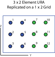
Rectangular subarray grid size, specified as a single positive integer, or a 1-by-2 row vector of positive integers.

If Grid size is an integer scalar, the array has an equal number of subarrays in each row and column. If Grid size is a 1-by-2 vector of the form [NumberOfRows, NumberOfColumns], the first entry is the number of subarrays along each column. The second entry is the number of subarrays in each row. A row is along the local y-axis, and a column is along the local z-axis. The figure here shows how you can replicate a 3-by-2 URA subarray using a Grid size of [1,2].

Dependencies

To enable this parameter, set Sensor array to Replicated subarray and Subarrays layout to Rectangular.

The rectangular grid spacing of subarrays, specified as a positive, real-valued scalar, a 1-by-2 row vector of positive, real-values, or Auto. Units are in meters.

  • If Grid spacing is a scalar, the spacing along the row and the spacing along the column is the same.

  • If Grid spacing is a 1-by-2 row vector, the vector has the form [SpacingBetweenRows,SpacingBetweenColumn]. The first entry specifies the spacing between rows along a column. The second entry specifies the spacing between columns along a row.

  • If Grid spacing is set to Auto, replication preserves the element spacing of the subarray for both rows and columns while building the full array. This option is available only when you specify Geometry as ULA or URA.

Dependencies

To enable this parameter, set Sensor array to Replicated subarray and Subarrays layout to Rectangular.

Positions of the subarrays in the custom grid, specified as a real 3-by-N matrix, where N is the number of subarrays in the array. Each column of the matrix represents the position of a single subarray in the array local coordinate system. The coordinates are expressed in the form [x; y; z]. Units are in meters.

Dependencies

To enable this parameter, set Sensor array to Replicated subarray and Subarrays layout to Custom.

Specify the normal directions of the subarrays in the array. This parameter value is a 2-by-N matrix, where N is the number of subarrays in the array. Each column of the matrix specifies the normal direction of the corresponding subarray, in the form [azimuth;elevation]. Angle units are in degrees. Angles are defined with respect to the local coordinate system.

You can use the Subarray positions and Subarray normals parameters to represent any arrangement in which pairs of subarrays differ by certain transformations. The transformations can combine translation, azimuth rotation, and elevation rotation. However, you cannot use transformations that require rotation about the normal.

Dependencies

To enable this parameter, set the Sensor array parameter to Replicated subarray and the Subarrays layout to Custom.

Extended Capabilities

C/C++ Code Generation
Generate C and C++ code using Simulink® Coder™.

Version History

Introduced in R2021a