Use Tilt Control on BBC micro:bit to Reach to a Target LED
This example shows you how to use a Simulink® model to build a simple game that uses tilt control on BBC micro:bit to reach to a target LED on the LED matrix, and see a happy face LED image upon success.
Introduction
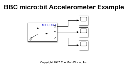
The Simulink® Coder Support Package for BBC micro:bit board provides blocks that represent the 5x5 LED matrix and the accelerometer sensor. In this example, you learn about a Simulink model that is designed to be a game for the BBC micro:bit board. This Simulink model performs the following functions:
Starts the game when you press a button on the BBC micro:bit board, and flashes a random LED that is the "target" of the game.
Reads the current accelerometer data (XY data) of the board and lights the corresponding LED on the LED matrix. The position of this active LED changes with the tilt of the board in different directions.
Displays a happy face LED image if the active LED matches the target LED (that is, accelerometer data and its LED mapping matches the target LED).
Prerequisites
If you are new to Simulink, complete the Interactive Simulink Tutorial and Getting started with Stateflow.
If you are new to Simulink Coder, visit the Simulink Coder product page for an overview and tutorials.
Complete Getting Started with Simulink Coder Support Package for BBC micro:bit.
Required Hardware
To run this example, you need this hardware:
BBC micro:bit board
USB type A to Micro-B cable (The one given with the BBC micro:bit board)
Open Model
Open the example model bbcmicrobit_accelLED_game.
Task 1 - Play the Game
1. In the Simulink model window, on the Hardware tab, click Build, Deploy & Start.
After you have successfully deployed the Simulink model on BBC micro:bit board, you can start playing the game.
2. Press button A on the BBC micro:bit board. A random LED lights for 1 second on the 5x5 LED matrix. This is the initial reference point (target).
3. Another LED lights based on the current position of the board.
4. Tilt the board in different directions. The position of the LED also changes based on the current position of the board.
5. When the LED matches the initial reference LED, a happy face LED image is displayed to indicate success.
Task 2 - Understand How the Simulink Model Works
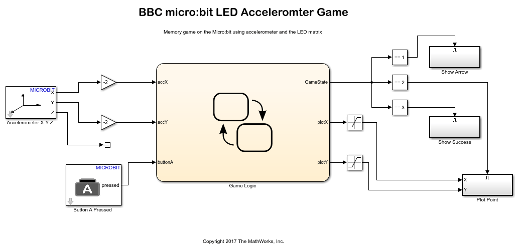
In the Simulink model, Game Logic is a Stateflow chart, which has three inputs and three outputs:
Input
buttonAtriggers the game when you press button A on the BBC Micro:bit board.Inputs
accXandaccYcorrespond to data from the Accelerometer X-Y-Z block, and they represent the current position of the board.Outputs
plotXandplotYare the outputs from the logic, and they light the corresponding LED based on the XY values.Output
GameStateis the output from the logic, and it represents the three output states of the game, based on the execution of logic in theGame LogicStateflow chart.
To understand the logic, open the Game Logic Stateflow chart in the Simulink model.
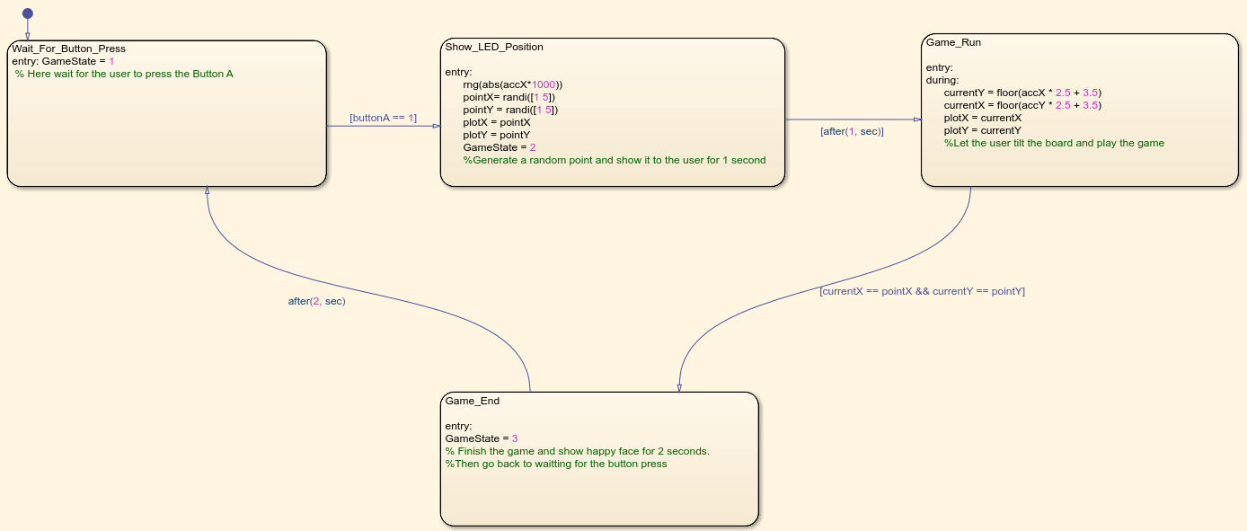
The Game Logic Stateflow chart contains states (modes of operation) and the logic for switching between the states.
1. In the first state (Wait_For_Button_Press), Stateflow waits for the player to press the button, which is monitored with the Button A pressed block. When the player presses the button, the second state is activated.
2. In the second state (Show_LED_Position), a random point is generated and stored in memory. This point is sent to the PlotXY block outside the Stateflow chart with the help of plotX and plotY outputs. After a wait time of 1 second, the third state becomes active.
3. In the third state (Game_Run), the accelerometer sensor values are read. These values translate to activation of an LED using the PlotXY block. The XY position is also compared with the one stored in memory. As long as the positions are not the same, the same state is active. (The player continues to tilt the board and observe the changing LED.)
Once the player reaches the initial reference (target LED), the fourth state is activated.
4. In the fourth state (Game_End), the Happy face LED image is shown for two seconds. State 1 is then reactivated. This completes one round, and the game can be continued.
The following topics provide a description of the logic used in the Simulink model.
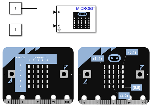
Showing a Single Point on the LED Matrix Using LED/PlotXY Block
The LED matrix can be split into rows and columns. An LED can be accessed by using its row number and column number. The LED/PlotXY block can light a single LED. For example, to light the LED in the first row and first column, input 1 to the X port and 1 to the Y port.
Reading the Accelerometer Data and Mapping the Tilt of the Board to the LED Matrix
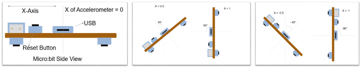
The accelerometer on the BBC micro:bit board measures the acceleration of the board along the X, Y, and Z directions. It can also be used to find the angle at which the board is tilted.
To understand the relationship between the accelerometer data and the tilt angle, monitorsignals and tune parameters of the model bbcmicrobit_accel_scope. Connect the hardware and on the Hardware tab, click Monitor & Tune.
While performing monitor and tuning actions, tilt the board slowly in X and Y directions and notice the values change from -1 to 1. Do not shake the board while doing this because it results in high acceleration.
When the BBC micro:bit board is tilted, the LED position has to shift proportionally to the tilt angle. This involves reading the accelerometer XY data and setting the LED position using PlotXY block.
Because the accelerometer output is from -1 to 1, and the LED matrix accepts values from 1 to 5, a modification of values needs to be done:
1. Multiply the accelerometer values by '2.5'. The new range is -2.5 to 2.5.
2. Add 3.5 to the preceding step. The new range is 1 to 6. The maximum LED matrix index is 5, so a value of 6 is addressed by using the saturation blocks outside of the Stateflow chart.
The range is calculated as: range = (accX * 2.5 + 3.5), where accX is the input from the Accelerometer block.
If the board is tilted left, the active LED moves left. If the board is tilted right, the LED moves right. Similarly, the LED shifts position forward and backward based on the forward or backward tilt. With this control, you can navigate to a desired LED position.
Using Enabled Subsystems
The output from the Game Logic Stateflow chart is connected to three enabled eubsystems: Show Arrow, Show Success, and Plot Point. Each enabled subsystem contains an Enable block that is dependent on the GameState output from the Stateflow chart.
The
Show Arrowsubsystem contains a PointLeft LED image block and a 5x5LEDMatrix block. This subsystem shows an arrow pointing to the Button A on the board when you are about to start the game.The
Plot Pointsubsystem contains the LED/PlotXY block. This subsystem lights an LED based on X and Y values when you are playing the game.The
Show Successsubsystem contains the Happy Face block and a 5x5LEDMatrix block. This subsystem shows the happy face LED image if you win the game.
Only one enabled subsystem is enabled by the Game Logic Stateflow chart at a time. The GameState output is a single synchronization output, which is updated in every state inside the Stateflow chart. Depending on the state of the Stateflow chart, the required block can be activated using a Compare to Constant block. If the GameState is equal to the constant in the Compare to Constant block, then that enabled subsystem is activated.
Using Gain Blocks at the Input
To avoid forcing players to tilt the board at a large angle to reach the outer points in the LED matrix, a Gain block is added before each of the accelerometer output values reaches the Game Logic Stateflow chart input. The gain is set to 2, which multiplies the accelerometer values by 2. With this modification, the tilt angle required to reach the extremes is reduced by half.
The new range can be calculated as:
New range = ((accX * 2) * 2.5 + 3.5)
The new range is from [-1.5 to 8.5]. The gain is set to -2. This reverses the direction of movement of LED with respect to the tilt. Try using 2 instead of -2, and note the difference.
Using Saturation Blocks at the Output
The range of accelerometer values are shifted from 1 to 6, to -1.5 to 8.5 using Gain blocks. However, this is out of range for the LED/PlotXY block. A Saturation block solves this, and the limits are set to 1 and 5. This means that if a X or Y value is greater than 5, the output will be 5, and if the values are less than 1, the output will be 1.
Other Things to Try
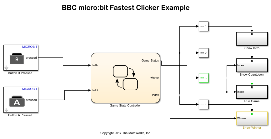
Create a game to determine the number of clicks on a button on the BBC micro:bit board.
Tip: You can design the game to be played by two people. See example model bbcmicrobit_two_button_game.