DVB-S2X HDL PL Header Recovery
This example shows how to extend the DVB-S2 time, frequency, and phase synchronization and PL header recovery mechanism to DVB-S2X using Simulink® blocks. These blocks are optimized for HDL code generation and hardware implementation.
Digital Video Broadcasting Satellite Second Generation Extended (DVB-S2X) modems operate in C (4-8 GHz), Ku (12-18 GHz), and Ka (26-40 GHz) frequency bands, same as DVB-S2. This example demonstrates how to leverage the DVB-S2 HDL receiver synchronization and extend the physical layer (PL) header recovery system to support DVB-S2X, which is backward compatible with DVB-S2. The model in this example reuses several synchronization components in DVB-S2, which include symbol timing synchronization, frame synchronization, coarse and fine frequency synchronization, phase offset estimation and correction, gain correction, noise variance estimation, and fine phase synchronization. By reusing these components, you can extend the PL header recovery is to support DVB-S2X. For more information on DVB-S2 synchronization and PL header recovery, see DVB-S2 HDL PL Header Recovery (Wireless HDL Toolbox). For a MATLAB® implementation of end-to-end DVB-S2X example, see the DVB-S2X Link Simulation with RF Impairments and Corrections for Regular Frames.
Model Architecture
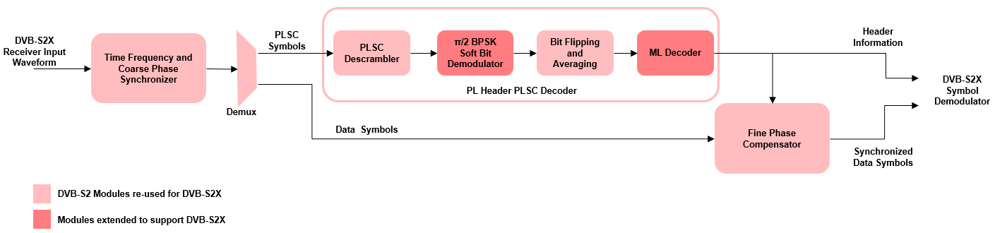
This section explains the high-level architecture of the model. The process begins with the DVB-S2X receiver input waveform streaming into the time frequency and coarse phase synchronizer. This module synchronizes the sequence to produce physical layer signaling code (PLSC) and data symbols. The PLSC descrambler then descrambles the PLSC symbols. Next, the descrambled symbols pass through a pi/2 binary phase shift keying BPSK soft bit demodulator, generating BPSK soft bits. The bit flipping and averaging module processes these bits. The maximum likelihood (ML) decoder then receives the output of the bit flipping and averaging module and recovers the header information. The fine phase synchronizer utilizes header information to perform synchronization on the data symbols, resulting in synchronized data symbols.
This block diagram shows the high-level architecture of the model.
File Structure
This example uses two Simulink models, five MATLAB files, and one Simulink data dictionary.
dvbs2xhdlPLHeaderRecovery.slx— Top-level Simulink model.dvbs2xhdlSyncPLHeaderRecoveryCore.slx— Model reference that synchronizes time, frequency, and phase, and decode PL Header.getdvbs2LDPCParityMatrices.m— Download the LDPC matrices.matfile.dvbs2hdlRxParameters.m— Generate parameters for thedvbs2xhdlSyncPLHeaderRecoveryCore.slxmodel reference.dvbs2hdlPhaseNoise.m— Introduce phase noise to the input sequence.dvbs2xhdlRxInit.m— Generate the transmitter waveform and initialize thedvbs2xhdlSyncPLHeaderRecoveryCore.slxmodel reference.dvbs2xhdlPLHeaderRecoveryVerify.m— Gather PL header parameters and compare with applied PL header parameters.dvbs2hdlReceiverData.sldd— Store bus signal configurations that come out of the model reference.
System Interface
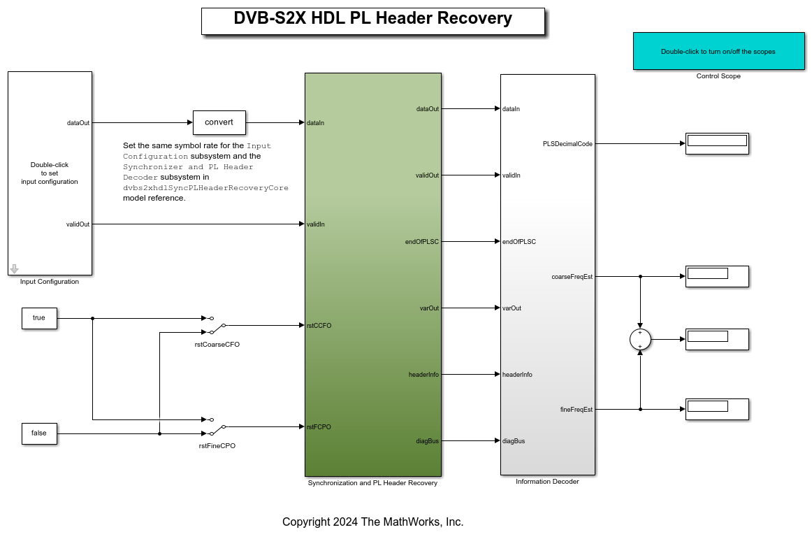
This figure shows the top-level overview of the dvbs2xhdlPLHeaderRecovery.slx model.
Model Inputs
dataIn — Input data, specified as an 18 bit complex data with a sample rate that is four times the symbol rate.
validIn — Control signal to validate the dataIn input port, specified as a Boolean scalar.
rstCCFO — Control signal to reset the coarse frequency compensation loop, specified as a Boolean scalar.
rstFCPO — Control signal to reset the fine phase compensation loop, specified as a Boolean scalar.
rstSS — Control signal to reset the symbol synchronizer loop, specified as a Boolean scalar.
Model Outputs:
dataOut — Decoded output symbols, returned as an 18 bit complex scalar.
validOut — Control signal to validate the dataOut output port, specified as a Boolean scalar.
endOfPLSC — Control signal to indicate the end of PLSC symbols in each synchronized frame, specified as a Boolean scalar.
nVar — Estimated noise variance, returned as a 32 bit complex scalar.
headerInfo — Bus signal to provide the PLS Decimal Code parameter of the PL header in each synchronized frame.
diagBus — Bus signal to provide the coarse frequency normalized with the sample rate, the fine frequency normalized with the symbol rate, the symbol synchronized output, the PLSC symbols, and the pilot symbols.
Model Structure
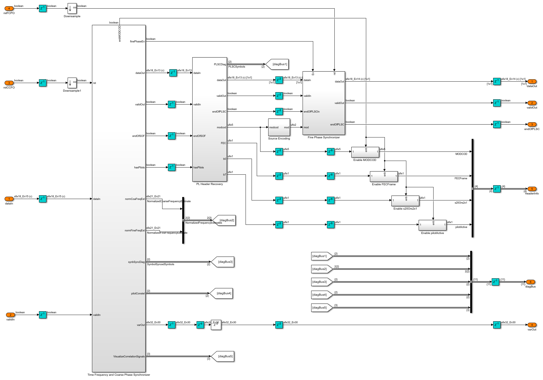
This figure shows the top-level model of the Synchronization and PL Header Recovery subsystem. It comprises Time Frequency and Coarse Phase Synchronizer, PL Header Recovery, and Fine Phase Synchronizer subsystems.
Time Frequency and Coarse Phase Synchronizer
This subsystem is same as that of DVB-S2. For detailed description about the Time Frequency and Coarse Phase Synchronizer subsystem, see the Time Frequency and Coarse Phase Synchronizer section in the DVB-S2 HDL PL Header Recovery (Wireless HDL Toolbox) example.
PL Header Recovery
The PL Header Decoder subsystem in the PL Header Recovery subsystem decodes the PLSC symbols of the PL header on a frame-by-frame basis to get the PLS Decimal Code parameter. This parameter indicates the modulation, coding scheme, and FECFrame type of the frame, as described in sections 5.5.2.2 and 5.5.2.3 of [ 1 ]. The PLSC symbols contain eight information bits that are bi-orthogonally encoded with a (64,8) code. The construction of the 64 bit code is such that each odd bit in the code is either always a flipped bit or equal to the even consecutive bit based on whether the pilots exist or does not exist in the frame respectively, as described in section 5.5.2.4 of [ 1 ]. The 64 encoded bits are pi/2-BPSK modulated as described in section 5.5.2 of [ 1 ]. The PL Frame Demultiplexer subsystem demultiplexes the PLSC symbols and the PL data frame symbols of the input. The signals from the hvalid and dvalid ports indicate the locations of PLSC symbols and PL data frame symbols respectively. The PLSC symbols are streamed into the PL Header Decoder subsystem.

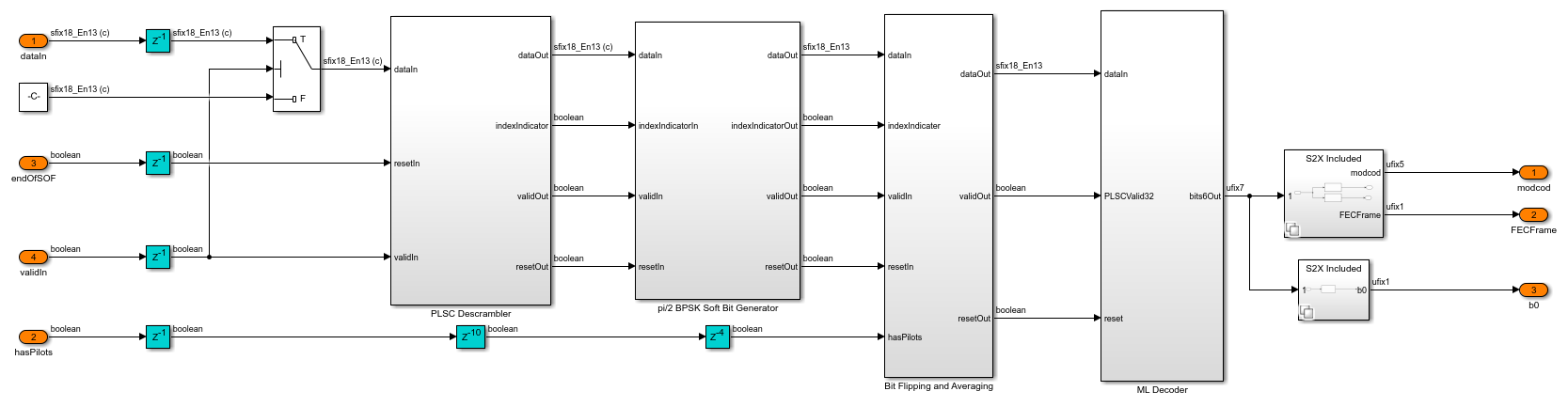
PL Header Decoder
The PLSC Descrambler subsystem in the PL Header Decoder subsystem descrambles the PLSC symbols. The signal from the indexIndicator port of the PLSC Descrambler subsystem distinguishes the even and odd locations of the PLSC symbols. The pi/2 BPSK Soft Bit Demodulator subsystem demodulates the PLSC symbols. If the pilots exist in the current PLFRAME, which is decided in the frame synchronization, the Bit Flipping and Averaging subsystem multiplies the odd soft bits by –1 in the PLSC symbols. A bit flip for a hard bit is same as multiplying by –1 for a soft bit. The subsystem averages the soft bits in even and odd locations to get one estimate. The subsystem generates 32 soft bits from 64 soft bits. A ML decoder decodes the (32,7) bi-orthogonal encoded bits. The system then uses the 7 decoded bits to construct PLS Decimal Code.
ML Decoder
The ML Decoder subsystem decodes the (32,7) bi-orthogonal code by selecting the maximum likelihood codeword. The subsystem enhances the DVB-S2 ML decoder, which decodes a (32,6) bi-orthogonal code, by adding a new row to handle the (32,7) bi-orthogonal code. The generator matrix for the DVB-S2X bi-orthogonal code includes a new zeroth row, in addition to the existing rows 1 through 6 from the DVB-S2 generator matrix. The DVB-S2X ML decoder operates similarly to the DVB-S2 system, as detailed in DVB-S2 HDL PL Header Recovery (Wireless HDL Toolbox) example. It identifies the maximum likelihood codeword by finding the minimum among the 128 Euclidean metrics. This codeword is then used to determine the PLS Decimal Code value.

While DVB-S2 has 2^6, which is equal to 64 possible codewords corresponding to 6 bits, DVB-S2X expands this to 2^7 which is equal to 128 possible codewords for 7 bits. By leveraging the new row stored in an LUT and the 64 codewords from DVB-S2, the system generates an additional 64 codewords, bringing the total to 128.

Fine Phase Synchronizer
This subsystem is same as that of DVB-S2. For detailed description about the Fine Phase Synchronizer subsystem, see the Fine Phase Synchronizer section in the DVB-S2 HDL PL Header Recovery (Wireless HDL Toolbox) example.
Run Model
Open the Input Configuration subsystem mask and set the symbol rate, PLS Decimal Code values, input stream format, user packet length and channel impairments on the Input Configuration subsystem mask and run the dvbs2xhdlPLHeaderRecovery.slx model. Alternatively, to run the model, execute this command at the MATLAB command prompt.
sim dvbs2xhdlPLHeaderRecovery
The PLS Decimal Code values must be a row vector. Each element of the row vector corresponds to a frame.
### Searching for referenced models in model 'dvbs2xhdlPLHeaderRecovery'.
### Total of 1 models to build.
### Starting serial model build.
### Successfully updated the model reference simulation target for: dvbs2xhdlSyncPLHeaderRecoveryCore

Build Summary

Model reference simulation targets:

Model                              Build Reason                                                          Status                        Build Duration
=====================================================================================================================================================
dvbs2xhdlSyncPLHeaderRecoveryCore  Target (dvbs2xhdlSyncPLHeaderRecoveryCore_msf.mexw64) did not exist.  Code generated and compiled.  0h 15m 1.3168s

1 of 1 models built (0 models already up to date)
Build duration: 0h 15m 22.773s


Number of frames synced = 147 out of 147
Initial frames not compared = 39
Number of frames lost due to PL header mismatch = 0 out of 108
Generate HDL Code
To generate the HDL code for this example, you must have HDL Coder™ license. Use makehdl and makehdltb commands to generate HDL code and HDL testbench for the Synchronization and PL Header Recovery subsystem. The testbench generation time depends on the simulation time.
The resulting HDL code is synthesized for a Xilinx® Zynq® UltraScale+ MPSoC ZCU102 evaluation board. The post place and route resource utilization are shown in this table. The maximum frequency of operation is 325 MHz.
      Resources      Usage
    _____________    _____

    CLB LUT          48743
    CLB Registers    79501
    RAMB36           22
    RAMB18           1
    DSP48            254
References
ETSI Standard EN 302 307-2 V1.3.1(2021). Digital Video Broadcasting (DVB); Second Generation Framing Structure, Channel Coding and Modulation Systems for Broadcasting, Interactive Services, News Gathering and other Broadband Satellite Applications; Part 2: DVB-S2 Extensions (DVB-S2X).
ETSI Standard TR 102 376-1 V1.2.1(2015-11). Digital Video Broadcasting (DVB); Implementation Guidelines for the Second Generation System for Broadcasting, Interactive Services, News Gathering and other Broadband Satellite Applications (DVB-S2).
Marco Luise and Ruggero Reggiannini, Carrier Frequency Recovery in All-Digital Modems for Burst-Mode Transmissions.
Michael Rice, Digital Communications - A Discrete-Time Approach, Prentice Hall, April 2008.