GPS HDL Legacy and L2C Waveform Generator
This example shows how to implement a global positioning system (GPS) legacy coarse/acquisition (C/A) code, precision (P) code, and L2 civilian (L2C) code waveform generator using Simulink® blocks. The Simulink model in this example is optimized for HDL code generation and hardware implementation.
GPS is a Global Navigation Satellite System (GNSS) that provides data to a GPS receiver. This data enables the receiver to determine its geolocation anywhere on or near the surface of the Earth. The receiver requires a line of sight to at least four satellites in the constellation. GPS signals contain navigation messages to calculate the position of the satellite in relation to a specific coordinate system, as well as the ranging codes to determine the distance between the satellite and the GPS receiver. The GPS signals L1 or L2 C/A, L2C in this example are intended for civilian use, while L1 or L2 P is allocated for military use. The standard carrier frequencies are L1 (10.23 MHz x 154 = 1575.42 MHz) and L2 (10.23 MHz x 120 = 1227.6 MHz). For more information, see [ 1 ].
For a MATLAB® version of this example and more details on legacy navigation (LNAV) and civil navigation (CNAV) data frame structures, see GPS Waveform Generation.
Model Architecture
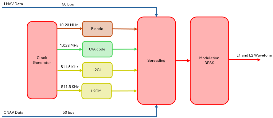
This figure shows the high-level architecture of the GPS waveform generator. By default, the waveform generator operates at a clock frequency of 32.768 MHz. The counters divide the clock frequency to generate frequencies of 10.23 MHz, 1.023 MHz, and 511.5 kHz. These frequencies drive the precision (P) code generator, coarse acquisition (C/A) code generator, and the L2 Civilian Moderate (L2CM) and L2 Civilian Long (L2CL) code generators. The LNAV data is spread using the P code and C/A code. The CNAV data is spread using the L2CM code and the resulting code is multiplexed with the L2CL code to obtain the final L2C spread code. These spread codes are then BPSK modulated to produce the L1 and L2 baseband waveforms.
This block diagram shows the high-level architecture of the model.
File Structure
This example uses a Simulink model and five MATLAB files.
gpshdlWaveformGenerator.slx— Top-level Simulink model.gpshdlWaveGenInit.m— Configure and initialize thegpshdlWaveformGeneratormodel.gpshdlRefWaveGen.m— Generate a reference waveform using thegpsWaveformGenerator.gpshdlWaveGenVerify.m— Compare Simulink output withgpshdlRefWaveGenreference and display the spectrum of waveform.HelperGPSNAVDataEncode.m— Helper file from Satellite Communications Toolbox to encode LNAV and CNAV data.HelperGPSNavigationConfig.m— Helper file from Satellite Communications Toolbox to configure LNAV and CNAV data.
System Interface
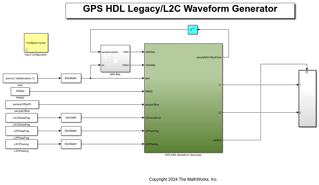
This figure shows the top-level overview of the gpshdlWaveformGenerator model.
Model Inputs
LNAVBits — Input LNAV data, specified as a Boolean vector. The sample rate is indicated by the signal from the sampleNAVinNextClock output port. The dimension of this signal corresponds to the number of satellites considered, ranging from 1 to 8.
CNAVBits — Input CNAV data, specified as a Boolean vector. The sample rate is indicated by the signal from the sampleNAVinNextClock output port. The dimension of this signal corresponds to the number of satellites considered, ranging from 1 to 8.
start — Control signal to start the module, reset the module and to sample the signals
PRNID,sampleOffset,L2CADataFlag,L2PDataFlag,L2CPhasing.PRNID — Input PRNID, specified as a 6 bit integer. The dimension of this signal corresponds to the number of satellites considered, ranging from 1 to 8.
sampleOffset — Input sampleOffset, specified as a 15 bit integer when output rate is 32.768 Msps, and 14 bit when output rate is 16.384 Msps or 10.24 Msps or 10.23 Msps. The dimension of this signal corresponds to the number of satellites considered, ranging from 1 to 8.
L2CADataFlag — Input L2 C/A data flag, specified as a 2 bit integer scalar.
L2PDataFlag — Input L2 P data flag, specified as a Boolean scalar.
L2CPhasing — Input L2 C phasing, specified as a Boolean scalar.
Model Outputs:
sampleNAVinNextClock — Signal to indicate when a NAV data bit is required. The dimension of this signal corresponds to the number of satellites considered, ranging from 1 to 8.
L1 — Baseband waveform on L1 carrier returned as a 16 bit complex data. The dimension of this signal corresponds to the number of satellites considered, ranging from 1 to 8.
L2 — Baseband waveform on L2 carrier returned as a 16 bit complex data. The dimension of this signal corresponds to the number of satellites considered, ranging from 1 to 8.
validOut — Control signal to indicate the validity of L1 and L2 baseband complex data, returned as a Boolean scalar.
Waveform Configurations
The section outlines the contents of the L2 waveforms, based on the L2 configurations.
The L2CPhasing — Decide whether the L2CM + Dc(t) with L2CL exists in phase or quadrature phase.
The L2CADataFlag — Decide whether the L2CM + Dc(t) with L2CL or C/A or C/A + D(t) exists in quadrature phase.
The L2PDataFlag — Decides whether the P(Y) or P(Y) + D(t) exists in phase.
Ranging Code Generators
P Code Generator
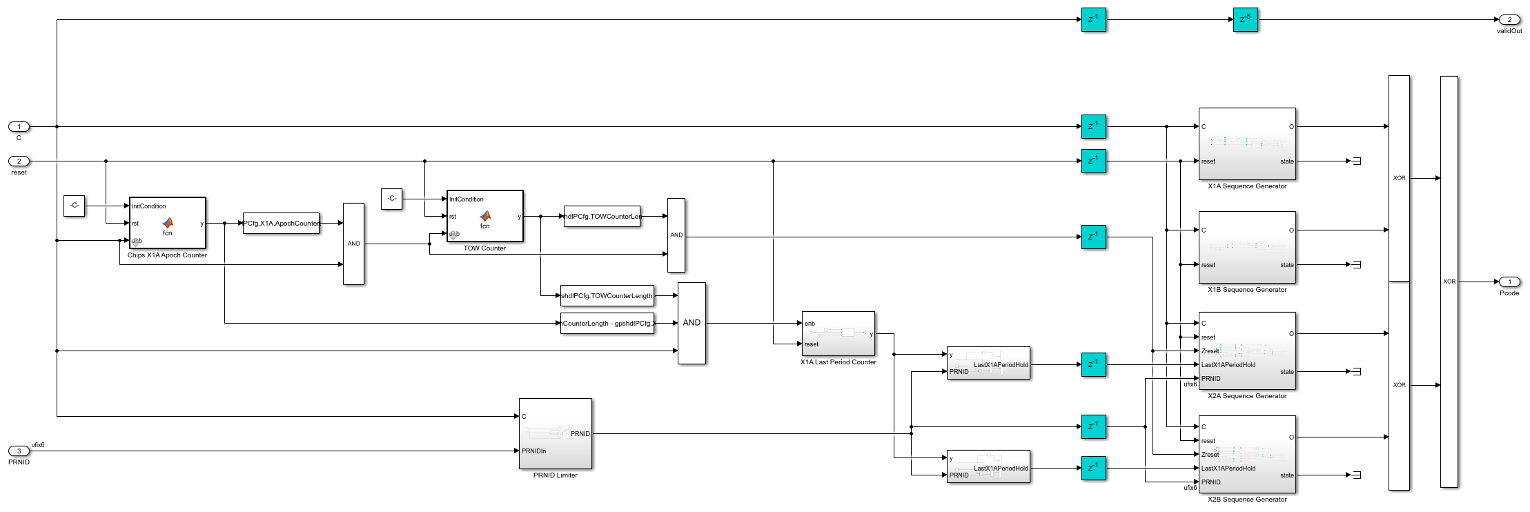
The Precision (P) code generator uses linear feedback shift register-based generators X1A, X1B, X2A, and X2B. The X1A and X2A generators are shortcycled to 4092 chips, running 3750 times to cover 1.5 seconds. The X1B and X2B generators are shortcycled to 4093 chips, running 3749 times and hold the last state to complete 1.5 seconds. The X2A and X2B hold the last state for an additional 37 chips. The X1 and X2 code chips are produced by modulo-2 addition of X1A with X1B and X2A with X2B, respectively. The X2i chip sequence is derived from a cyclic delay of the X2 sequence, as specified in Table 3-Ia of [ 1 ], with each i corresponding to a specific PRNID. The final P code chips are formed by modulo-2 addition of the X1 and X2i chips, with a chip rate of 10.23 MHz. The P Code generator repeats itself after a week.
This table provides information about the initial states, polynomials, for the X1A, X1B, X2A, and X2B code generators in P code generator, as defined in [ 1 ].
      Parameter           X1A Value                      X1B Value                                   X2A Value                              X2B Value
    _____________    ___________________    ____________________________________    ____________________________________________    __________________________

    Initial State    584                    1364                                    2341                                            1364
    Polynomial       1+x^6+x^8+x^11+x^12    1+x^1+x^2+x^5+x^8+x^9+x^10+x^11+x^12    1+x^1+x^3+x^4+x^5+x^7+x^8+x^9+x^10+x^11+x^12    1+x^2+x^3+x^4+x^8+x^9+x^12
Table 3-VI of [ 1 ] details the states of the X1B, X2A, and X2B code generators during the final 0.4 ms of the 7-day period. Each generator maintains its last state until the end of the 7-day cycle.
C/A Code Generator
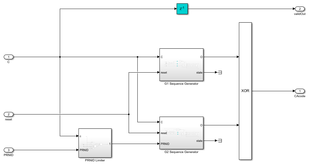
The Coarse Acquisition (C/A) code generator uses linear feedback shift register-based generators, G1 and G2. A cyclic delay of the G2 sequence, as specified in Table 3-Ia of [ 1 ], derives the G2i chip sequence, with each delay corresponding to a specific PRNID. The generator forms the final C/A code chips by performing modulo-2 addition of the G1 and G2i chips, with a chip rate of 1.023 MHz. The C/A code generator repeats every 1 ms.
This table provides information about the initial states, polynomials, for the G1 and G2 code generators in P code generator, as defined in [ 1 ].
      Parameter       G1 Value              G2 Value
    _____________    __________    __________________________

    Initial State    1023          1023
    Polynomial       1+x^3+x^10    1+x^2+x^3+x^6+x^8+x^9+x^10
L2CM and L2CL Code Generators
The L2 Civilian Moderate (L2CM) and L2 Civilian Long (L2CL) signals use a modular 27-bit shift register. The PRNID determines the initial state for each register, as outlined in Table 3-II of [ 1 ]. Both generators use the polynomial 1 + x^3 + x^4 + x^5 + x^6 + x^9 + x^11 + x^13 + x^16 + x^19 + x^21 + x^24 + x^27. The L2CM signal shortcycles to 10,230 chips, while the L2CL signal shortcycles to 767,250 chips. The chip rate is 511.5 KHz. The L2CM and L2CL generators repeat every 20 ms and 1.5 seconds, respectively.
Run Model
Run the gpshdlWaveformGenerator Simulink model to initialize, run, verify the example. You can configure the input on the Input Configuration subsystem.
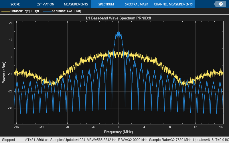
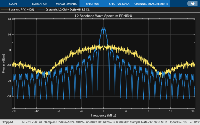
Verify Results
Input PRNIDs: 8   9  15  18

Given sample offset at output rate 32.768 MHz: 23940  14543  11726  21880

Equivalent C/A code phase offset: 275.6056      568.9751      656.9203      339.9177

Mean square error with SatComm reference for L1 waveform for PRNID: 8
Real: -193.55        Imag: -Inf

Mean square error with SatComm reference for L1 waveform for PRNID: 9
Real: -193.55        Imag: -Inf

Mean square error with SatComm reference for L1 waveform for PRNID: 15
Real: -193.55        Imag: -Inf

Mean square error with SatComm reference for L1 waveform for PRNID: 18
Real: -193.55        Imag: -Inf


Mean square error with SatComm reference for L2 waveform for PRNID: 8
Real: -168.1167        Imag: -Inf

Mean square error with SatComm reference for L2 waveform for PRNID: 9
Real: -168.1098        Imag: -Inf

Mean square error with SatComm reference for L2 waveform for PRNID: 15
Real: -168.1017        Imag: -Inf

Mean square error with SatComm reference for L2 waveform for PRNID: 18
Real: -168.1048        Imag: -Inf
Generate HDL Code
To generate the HDL code for this example, you must have HDL Coder™ license. Use makehdl and makehdltb commands to generate HDL code and HDL testbench for the Synchronization and PL Header Recovery subsystem. The testbench generation time depends on the simulation time.
The resulting HDL code is synthesized for a Xilinx® Zynq® UltraScale+ MPSoC ZCU102 evaluation board. The post place and route resource utilization are shown in this table. The maximum frequency of operation is 476 MHz.
      Resources      Usage
    _____________    _____

    CLB LUT          5032
    CLB Registers    2965
    RAMB36           0
    RAMB18           8
    DSP48            0
References
IS-GPS-200, Rev: N. NAVSTAR GPS Space Segment/Navigation User Segment Interfaces. Aug 22, 2022; Code Ident: 66RP1.
Further Exploration
To enhance the GPS HDL waveform generation example and expand its capabilities, you can the integrate additional GPS signals, L1C and L5, to provide more comprehensive signal coverage. Furthermore, you can create a more robust testing environment by simulating the channel impairments such as additive white Gaussian noise (AWGN), Doppler frequency offsets and drifts using GPS HDL Reference Applications Overview (Wireless HDL Toolbox).