Receiver Position Estimation Using Range and Range-Rate Measurements in NTN Systems
This example demonstrates how to determine the immediate approximate position of a receiver on the surface of the Earth using range and range-rate data from a single low Earth orbit (LEO) satellite for satellite-based non-terrestrial network (NTN) systems. The accuracy of the measurements directly affects the precision of the position estimation. With range and range-rate data from a single satellite, you can identify two possible receiver positions. To resolve this position ambiguity, you must have additional information, and this example assumes that the direction of the antenna beam is known. In situations where the global navigation satellite system (GNSS) signal is weak or unavailable, or where the receiver lacks a GNSS module, you can use such non-GNSS-based positioning techniques. To provide satellite access to receivers independently of GNSS, the Third Generation Partnership Project (3GPP) has included a study item in Release 19 [5].
Setup Simulation
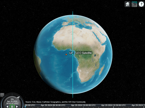
This example creates a satellite scenario with an LEO satellite at 600 km moving in a circular orbit, as described in 3GPP TR 38.811 [1], and a receiver at Null Island (0 degrees latitude and 0 degrees longitude). From this point on, this example refers to the receiver as a user equipment (UE).
% Create a scenario
sc = satelliteScenario;
sc.StartTime = datetime(2024,4,29,09,01,57); % In datetime
sc.StopTime = sc.StartTime + hours(2);
sc.SampleTime = 60;                          % In seconds

% Add satellite to the scenario
satAltitude = 600e3;                         % In meters
earthRadius = physconst("EarthRadius");      % In meters
semiMajorAxis = earthRadius + satAltitude;   % In meters
eccentricity = 0;                            % Circular orbit (e = 0)
inclination = 90;                            % In degrees
raan = 0;                                    % Right ascension of ascending node, in degrees
argOfPeriapsis = 0;                          % In degrees
trueAnomaly = 0;                             % In degrees
sat = satellite(sc,semiMajorAxis, ...
    eccentricity, ...
    inclination, ...
    raan, ...
    argOfPeriapsis, ...
    trueAnomaly, ...
    Name="LEO Satellite", ...
    OrbitPropagator="two-body-keplerian");

% Add a UE to the scenario, using groundStation function
lat = 0;
lon = 0;
altitude = 0;
ue = groundStation(sc,lat,lon, ...
    Altitude=altitude, ...
    Name="UE");

% Visualize scenario
viewer = satelliteScenarioViewer(sc);
Calculate Range and Range-Rate
The example enables you to use values of range and range-rate from the scenario or use the measured values of latency and Doppler shift for a received 5G signal. To use the ideal values for range and range-rate taken directly from the satellite scenario, specify measurementMode as "scenario". If you have a 5G Toolbox™, you can specify measurementMode as "5G signal" to generate a 5G physical downlink shared channel (PDSCH) signal and pass it through an ITU-R P.681 LMS channel [3]. Use the PDSCH demodulation reference signal (DM-RS) to estimate the delay and Doppler. Calculate the range from the propagation delay of the signal and determine the range-rate from the Doppler shift of the signal.
To ignore the Earth rotation rate, as mentioned in 3GPP TR 38.821 [2], you can use the aer and dopplershift object functions to compute and model the range and range-rate from the satellite scenario.
measurementMode ="scenario"; % "scenario" or "5G signal"
Setting measurementMode to scenario enables you to add measurement errors by specifying the mean and standard deviation of each error. The mean and standard deviation follow the Gaussian distribution.
if measurementMode == "scenario" addMeasurementError =false; rangeErrorStats = [0 30]; % [Mean StandardDeviation] in meters rangeRateErrorStats = [0 3]; % [Mean StandardDeviation] in meters per second end
The queryTime variable specifies the time instances of the scenario for which to measure and model the range and range-rate. For measurements to be valid at queryTime, the satellite must be visible to the UE. To have a valid queryTime, perform access analysis, and select a time during which access is present.
% Perform access analysis
ac = access(sat,ue);
[status,timeout] = accessStatus(ac);
statusIdx = find(status,1);
if isempty(statusIdx)
    disp("Position estimation cannot be performed " + ...
        "as there is no access between satellite and UE.")
    return
end
% Remove the access object to avoid clutter in the viewer
delete(ac)

queryTime = timeout(statusIdx(1));
% Get the elevation and range using the aer function
[~,el,r] = aer(ue,sat,queryTime);
% Calculate the Doppler shift and range-rate using the dopplershift function
carrierFrequency = 2e9;                           % In Hz
[fshift,~,dopplerInfo] = dopplershift( ...
    sat,ue,queryTime,Frequency=carrierFrequency);
rangeRate = -1*dopplerInfo.RelativeVelocity;

% Calculate the states of the satellite in ECEF
[satPos,satVel] = states(sat,queryTime,CoordinateFrame="ecef");

% When you specify measurementMode as "5G signal", transmit the signal,
% pass it through a channel, and estimate the latency and Doppler shift.
rng(0)
lightspeed = physconst("lightspeed");
if strcmpi(measurementMode,"5G signal")
    % Transmit the signal
    frameDurInSeconds = 10e-3; %#ok<*UNRCH>
    delayInSeconds = r/lightspeed;
    nFrames = ceil(delayInSeconds/frameDurInSeconds) + 1;
    carrier = nrCarrierConfig;
    pdsch = nrPDSCHConfig;
    pdsch.DMRS.DMRSAdditionalPosition = 2;
    [txWaveform,waveformInfo] = ...
        HelperNRNTNThroughput.generatePDSCHWaveform( ...
        carrier,pdsch,struct,eye(pdsch.NumLayers),"double",carrier.SlotsPerFrame*nFrames);
    refGridAllSlots = waveformInfo.ResourceGrid;

    % Model delay
    delayInSamples = delayInSeconds.*waveformInfo.SampleRate;
    integDelaySamples = floor(delayInSamples);
    fracDelaySamples = (delayInSamples - integDelaySamples);
    staticDelay = dsp.Delay(Length=integDelaySamples);
    variableFractionalDelay = dsp.VariableFractionalDelay( ...
        InterpolationMethod="Farrow", ...
        FarrowSmallDelayAction="Use off-centered kernel", ...
        MaximumDelay=1);

    % Apply fixed (static) delay
    delayedTx = staticDelay(txWaveform);
    % Apply variable fractional delay
    delayedTx = variableFractionalDelay(delayedTx,fracDelaySamples);

    % Pass the delayed signal through a channel
    channel = p681LMSChannel;
    channel.SampleRate = waveformInfo.SampleRate;
    channel.CarrierFrequency = carrierFrequency;
    channel.SatelliteDopplerShift = fshift;
    channel.MobileSpeed = 0;
    channel.ElevationAngle = el;
    channel.RandomStream = "mt19937ar with seed";
    rxWaveform = channel(delayedTx);

    % Measure the latency and Doppler shift
    freqSearch = 0.999*fshift:sign(fshift):1.001*fshift;
    [delayEstSamples,fshiftEst] = HelperNRNTNThroughput.jointTimeFreq( ...
        carrier,rxWaveform,refGridAllSlots,freqSearch);

    % Get the estimated range and range-rate
    rangeEst = delayEstSamples*lightspeed/waveformInfo.SampleRate;
    rangeRateEst = -1*fshiftEst*lightspeed/carrierFrequency;
else
    % Get the estimated range and range-rate from scenario
    rangeEst = r;
    rangeRateEst = rangeRate;
    if addMeasurementError == 1
        rangeEst = rangeEst - (rangeErrorStats(1) + ...
            randn(1)*rangeErrorStats(2));
        rangeRateEst = rangeRateEst - (rangeRateErrorStats(1) + ...
            randn(1)*rangeRateErrorStats(2));
    end
end
Estimate Position
The example estimates the position of the UE using the technique described in [4]. This technique provides two locations for a UE. These locations lie on opposite sides of satellite sub-track, which leaves the UE position ambiguous.
uePositions = HelperNTNPositionEstimate.instantposition( ...
    satPos,satVel,rangeEst,rangeRateEst);                      % Each column is LLA (Latitude, Longitude, Altitude)
disp(uePositions)
    0.9438         0
   13.9726    0.0000
   -0.0779         0
Calculate the position error for each estimated position.
errors = HelperNTNPositionEstimate.positionerror([lat; lon; altitude],uePositions);
if any(uePositions)
    disp("Position error with estimated position 1: " + num2str(errors(1) + " meters"))
    disp("Position error with estimated position 2: " + num2str(errors(2) + " meters"))
else
    disp("No possible UE position with the given measurements.")
    return
end
Position error with estimated position 1: 1554977.4155 meters
Position error with estimated position 2: 5.8158e-10 meters
View the estimated positions in the Satellite Scenario Viewer.
ueNames = "Estimated UE Position " + (1:size(uePositions,2))';
ueEstPos = groundStation(sc,uePositions(1,:),uePositions(2,:), ...
    Altitude=uePositions(3,:),Name=ueNames);

Resolve Position Ambiguity
To determine the UE position based on the two estimates, you must gather additional information. In this example, resolves the UE position ambiguity by assuming the known satellite antenna beam, on which the UE has received the signal, thereby limiting the UE position to the coverage area for that particular beam. Follow these steps to determine the position of the UE based on the known satellite antenna beam:
Add a conical sensor to the satellite in the scenario to model the coverage of the known beam. Match the maximum view angle of the conical sensor to the beamwidth of the antenna.
Point the conical sensor to the actual UE position, to ensure it covers the expected area.
Add a ground station at both possible UE locations.
Perform access analysis between the satellite and each of the possible UE locations.
Select the UE location that has satellite access.
If both possible positions have satellite access, you cannot determine the UE position without further information. In such cases, the UE considers both positions as possible estimates. If neither position has satellite access, then the UE considers both positions to be outside the coverage area, and does not select either position.
% Add a conical sensor to the satellite, pointing to the UE.
% Spot beams for LEO satellites typically have a beamwidth ranging from 1
% to 5 degrees, and for GEO satellites, the range is from 0.2 to 2 degrees.
% This example uses a beamwidth of 1 degree, as it applies to a wide
% variety of scenarios. You can define the half-angle field of view of the
% cone with the MaxViewAngle property. Setting MaxViewAngle to half of the
% beamwidth ensures expected coverage.
gimbalSat = gimbal(sat);
pointAt(sat,ue)
maxViewAngle = 0.5;                                      % In degrees
cs = conicalSensor(gimbalSat,MaxViewAngle=maxViewAngle);
% View the coverage area
fieldOfView(cs);

% Add the expected user positions, ignoring the negative altitudes.
% Ignoring negative altitude avoids blockage from the Earth surface while
% performing access analysis.
delete(ueEstPos)
ueEstPos = groundStation(sc,uePositions(1,:),uePositions(2,:), ...
    Name=ueNames,Altitude=max(uePositions(3,:),0));

% Add access from the satellite conical sensor to the UE positions
accessSatUE = access(cs,ueEstPos);

% Compute access analysis for each access using accessStatus method
status = accessStatus(accessSatUE,queryTime);

% Select the position based on access analysis
selectedPosIdx = [];
finalPos = [];
if all(status)
    disp("Position ambiguity has not been resolved. Both UE positions are within the coverage area.")
elseif any(status)
    selectedPosIdx = find(status,1);
    disp("Position ambiguity has been resolved. Only the UE with position " + selectedPosIdx + " is within the coverage area.")
    finalPos = uePositions(:,selectedPosIdx);
else
    disp("No UE position is within the coverage area.")
end
Position ambiguity has been resolved. Only the UE with position 2 is within the coverage area.
disp(finalPos)
   1.0e-14 *

         0
    0.5224
         0
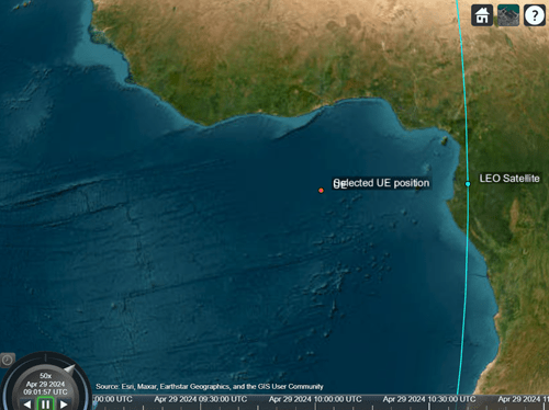
Visualize the resolved position in the Satellite Scenario Viewer by deleting the other assets.
% Delete the other assets of the scenario
if ~isempty(finalPos)
    delete(accessSatUE)
    delete(ueEstPos)
    finalUE = groundStation(sc,finalPos(1),finalPos(2), ...
        Altitude=finalPos(3),Name="Selected UE position");
    errorsFinal = HelperNTNPositionEstimate.positionerror([lat; lon; altitude],finalPos);
    disp("Position error with selected position: " + num2str(errorsFinal(1) + " meters"))
end
Position error with selected position: 5.8158e-10 meters
Further Exploration
By using instant coarse position estimation in NTN, you can expand this example in these ways:
Evaluate the position error across various satellite orbits and UE locations.
Investigate how measurement errors affect the accuracy of position estimation.
Switch
measurementModeto"5G signal"to estimate the position with the measured latency and Doppler using a 5G demodulation reference signal (DM-RS).
Supporting Files
The example uses these supporting files:
HelperNTNPositionEstimate.m— Class that defines the supporting functions used in this example for position estimation.HelperNRNTNThroughput.m— Class that defines the supporting functions used in this example for 5G measurement mode.
References
[1] 3rd Generation Partnership Project (3GPP). 3GPP TR 38.811. "Study on new radio (NR) to support non-terrestrial networks." 3rd Generation Partnership Project; Technical Specification Group Radio Access Network. 3GPP: September 2020.
[2] 3rd Generation Partnership Project (3GPP). 3GPP TR 38.821. "Solutions for NR to support non-terrestrial networks (NTN)." 3rd Generation Partnership Project; Technical Specification Group Radio Access Network. 3GPP: March 2023.
[3] International Telecommunication Union (ITU). ITU-R Recommendation P.681-11. "Propagation data required for the design systems in the land mobile-satellite service." P Series; Radio wave propagation. ITU: August 2019.
[4] Levanon, Nadav. "Instant Active Positioning with One LEO Satellite." Navigation 46, no. 2 (June 1999): 87–95. https://doi.org/10.1002/j.2161-4296.1999.tb02397.x.
[5] 3rd Generation Partnership Project (3GPP). 3GPP TR 22.865. "Study on satellite access Phase 3." 3rd Generation Partnership Project; Technical Specification Group Services and System Aspects. 3GPP: December 2023.