Calculate SNDR and RLM with IBIS-AMI Simulator
This example shows how to calculate the signal-to-noise and distortion ratio (SNDR) and ratio of level mismatch (RLM) for waveforms generated by the IBIS-AMI simulator Serial Link Designer. SNDR and RLM are important metrics for standards such as PCIe6 and PCIe7 [1] as well as IEEE 802.3 and OIF-CEI interface standards.
The metric calculations use multi-pulse fit response (MPFR)-based methodologies. This calculation involves extracting pulse responses from the transmitter output compliance pattern waveform. This approach reduces the impact of channel loss and duty cycle distortion from the metric calculation. The SNDR metric is the ratio of the signal strength to the noise and distortion. The signal strength is quantified by the effective pulse response maximum. The random noise is extracted through comparison of the compliance pattern repetitions. The distortion term comes from the pulse fit error. The RLM metric comes from quantifying the difference between the observed PAM4 symbol voltages to their ideal level separation. The SNDR must be at least 34 dB and RLM at least 0.95 to meet compliance for both PCIe6 and PCIe7.
This example is part of a collection of three examples where the SNDR and RLM calculations are featured. Calculate SNDR and RLM with SerDes Simulink Model, illustrates how to generate PCIe7 transmitter compliant output waveforms and calculate SNDR and RLM from Simulink simulation results. Calculate SNDR and RLM with System Object Scripting, illustrates how to generate waveforms with MATLAB scripting and calculate SNDR and RLM.
The Serial Link Designer project TxPCIe7 has a single PCIe7 transmitter, a lossy 2.5-inch differential transmission line to represent a package model of about 10 dB of loss at 32 GHz and a simple receiver probe. The eight distinct PCIe6/7 transmitter compliance data patterns are defined and available for use.
Set Up Signal Integrity Project
Define project name.
projectName = 'TxPCIe7';Define sheet name.
sheetname = 'sheet1';Define the time domain stop time, record start and the record symbols (or bits).
recordStart = 10e3; % UI
recordBits = 90e3; % UI
timeDomainStop = 100e3; % UI
Define the PCIe6/7 transmitter compliance data pattern. Valid lane values are integers from 0 to 7.
compliancePatternLane = 0;
The first time you run the example, unzip the Serial Link Designer project.
% Unzip project directory if not already unzipped.
localDir = dir(pwd);

dirNames = {localDir.name};
isdir = [localDir.isdir];

dirNameTest = strcmp(dirNames,projectName);
zipNameTest = strcmp(dirNames,[projectName,'.zip']);

if any(zipNameTest) && all(~dirNameTest)
    % If the zip exists, and a folder with the matching name does not
    % exist, then unzip the compressed file.
    unzip([projectName,'.zip'])
end
Open the project and set parameters to ensure that time domain analysis is run. Enable only the specified sheet.
% Open signal integrity project
sip = SignalIntegrityProject(projectName,'openApp',true);

% Simulation setup
sip.simulationSetup(...
    'pre',true,...
    'validation',true,...
    'generateNetlists',true,...
    'includeStatisticalAnalysis',true,...
    'includeTimeDomainAnalysis',true,...
    'runSpice',false,...
    'performChannelAnalysis',true,...
    'waveformAnalysis',false,...
    'timingAnalysis',false);

sip.SimulationParameters("Record Start")=recordStart;
sip.SimulationParameters("Record Bits")=recordBits;
sip.SimulationParameters("Time Domain Stop")=timeDomainStop;

% Disable all sheets
for ii = 1:length(sip.Sheets)
    sip.Sheets(ii).Included = false;
end

% Check if sheetname is valid
if ~any(strcmp([sip.Sheets.Name],sheetname))
    allSheets = [sip.Sheets.Name]';
    allSheetsStr = sprintf('%s\n',allSheets);
    error('Requested sheetname "%s" not found. Valid sheet names include:\n%s',...
        sheetname,allSheetsStr(1:end-1))
end

% Enable desired sheet
sh = sheet(sip,sheetname);
sh.Included = true;

% Set stimulus pattern.  Assumes data pattern name structure.
stimulusPatternName = sprintf('lane%i',compliancePatternLane);
sh.designator('Tx1').Stimulus = stimulusPatternName;

% Get symbol data pattern vector
DataPattern = si.PCIeCompliancePattern(compliancePatternLane);
Run Simulation
Run the simulation to generate the transmitter package output waveform.
run(sip)
Extract Simulation Results
Extract the simulation results including symbol time, sample interval, and the waveform after the package channel model.
% Get the first simulation result
sim = sh.Simulations(1);
if isempty(sim)
    error('Need to simulate first');
end

% Extract the symbol time from the Tx1 designator
uiStr = char(sh.designator('Tx1').UI);
timeStrings = {'fs','ps','ns','us','ms';1e-15, 1e-12, 1e-9, 1e-6, 1e-3};
unitNdx = find(strcmp(timeStrings(1,:),uiStr(end-1:end)));
if isempty(unitNdx)
    error('SymbolTime not found.  Specify manually below.')
end
SymbolTime = str2double(uiStr(1:end-2))*timeStrings{2,unitNdx(1)};

% Determine index to time domain waveforms
ndx = strcmpi([sim.Waveforms.Title],'TimeDomain: waveform');

if all(~ndx)
    error('Need to include time domain in simulation.')
end

% Get waveform table
waveTable = sim.Waveforms(ndx).table;

% Get simulation sample interval
sampleInterval = waveTable.Time(2) - waveTable.Time(1);

% Get the BRX1 columns of results
ndxBRX1 = find(strncmpi(waveTable.Properties.VariableNames,'V(BRX1',5));

% Select the first of the BRX1 columns
waveFull = waveTable{:,ndxBRX1(1)};
SNDR and RLM Calculation
Input the waveform and parameters to the sndr object to calculate the SNDR and RLM metrics.
sndrObj = sndr('Wave',waveFull,...
    'InputSampleInterval',sampleInterval,...
    'DataPattern',DataPattern,...
    'SymbolTime',SymbolTime);
Utilize report method to observe the metric values. These results show that the system under test complies with the PCIe7 SNDR requirement of at least 34 dB, while the RLM metric is below the required 0.95 value.
report(sndrObj)
For Standard=PCIe
SNDR = 35.3132 dB
	Pmax (Effective) = 258.984 mV
	SigmaNoise = 3.21576 mV
	SigmaError = 3.06489 mV
RLM = 0.946839
	V0 = -224.006 mV
	V1 = -74.6504 mV
	V2 = +70.6992 mV
	V3 = +224.006 mV
Compare injected RLM value to measured RLM value.
RLMndx = strcmpi(sim.Results.Properties.VariableNames,'TX1:RLM.injectedRLM');
injectedRLM = sim.Results{1,RLMndx};
disp("Input RLM = " + injectedRLM + ", Measured RLM = " + sndrObj.RLM);
Input RLM = 0.95, Measured RLM = 0.94684
Close out the signal integrity project.
closeApp(sip)
Ideas for Further Exploration
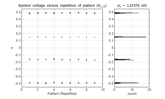
Use the sndr plot methods, plotDataPattern, plotAveragingResults, plotWaveResampled, plotSigmaNoise, plotVLik, plotLPFR, plotMPFROddEven, or plotMPFR4 to better understand the metric computational process. For example, the following command illustrates the voltage samples used to calculate the random noise standard deviation:
plotSigmaNoise(sndrObj)
What impact does adding SJ to the system make to the averaging results plot and the VLik plot? Try the plotting methods
plotVlik(sndrObj)andplotSigmaNoise(sndrObj).How does having a non-ideal Q0 Tx FFE setting impact the metrics?
How much does the SNDR and RLM metrics change as the data pattern 'lane' parameter is changed from 0 through 7?
How does adding RJ and DJ jitter influence the metrics?
How does package loss and/or characteristic impedance and termination impedance impact the metrics?
What system parameters have the largest impact on the RLM metric beyond the bias voltage injected by the RLM block?
What factors impact the magnitude of the fit error?
How does increasing the number of waveform repetitions to more than 250, as called for by the spec, change the metric calculation? The compliance pattern is 8768 symbols long, so the number of symbols to simulate would be more than 2,192,000 symbols.
How does the SNDR and RLM metrics change due to samples per symbol changes and as
sndrresampling method changes from 'spline' to 'linear'?
How To Modify Your Serial Link Designer Project
You can apply this same approach to calculate the SNDR and RLM of your own Serial Link Designer project. For PCIe7 compliant metrics, you must utilize special data patterns. The following instructions illustrate how to enable these.
With a file explorer:
From the example TxPCIe7 project directory, browse to the \si_lib\patterns\ directory.
Copy the file PCIeLane0Map0132.txt to your own project \si_lib\patterns\ directory.
From Serial Link Designer:
Open the desired sheet.
Double click on Tx1 to bring up Designator Element Properties.
Click "Stimulus" button > Click "New" button.
Give it the name "lane0".
Set the number of modulation levels to 4.
Specify the mapping to be "PAM4_0132".
Choose the File radio button and select the file PCIeLane0Map0132.txt
Press Ok.
On the Designator Element Properties window for TX1 update the Stimulus column to select "lane0" instead of "default_pattern".
Close.
References
[1] PCI-SIG, https://pcisig.com.