Circuit Envelope Fundamentals
R2026bThe circuit envelope technique speeds up RF system simulation. In Simulink®, simulating high-frequency signals requires a time step proportional to the highest frequency present in the RF system. However, the modulation frequency or envelope of the RF signals can be several orders of magnitude smaller than the highest frequency. The circuit envelope technique takes advantage of this condition to model RF signals accurately while reducing simulation time. For more information on envelope signal representation, see Circuit Envelope Basics.
To learn how to build an RF system using the circuit envelope library, see Getting Started with RF Modeling.
Blocks
 | Continuous Wave | Model constant envelope source |
 | Noise | Model noise using current or voltage noise source in RF systems |
 | Sinusoid | Model DC offset and sinusoidal modulation |
 | Configuration | Define system simulation settings |
 | Inport | Convert Simulink input signal to RF Blockset signal |
 | Outport | Convert RF Blockset signal to Simulink output signals |
 | Connection Port | Connection port for RF subsystem |
 | Ground | Simulate connection to electrical ground |
 | Spectrum Analyzer | Display frequency spectrum of time-domain signals |
 | Connection Label | Virtual connection between circuit envelope ports (Since R2022a) |
Topics
- Circuit Envelope Basics
Introduction, assumptions, advantages, definition, and work flow of Circuit Envelope simulation.
- Circuit Envelope Library
Learn about Circuit Envelope library environment.
- Simulate High Frequency Components
Example showing circuit envelope simulation techniques.
- Model RF Mixer
Expose various workflows for modeling RF systems using an RF mixer example.
Related Information
Featured Examples
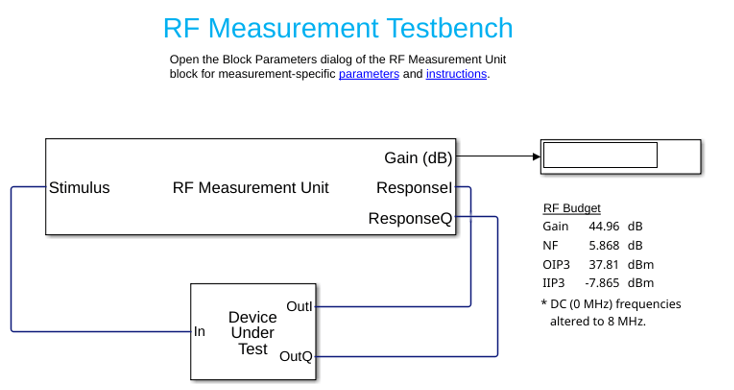
Getting Started with RF Modeling
Build a simple RF receiver and perform circuit envelope simulation.
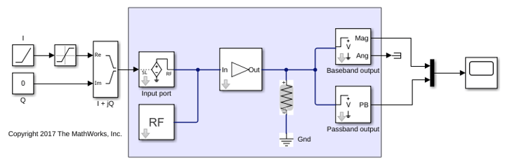
Passband Signal Representation in Circuit Envelope
Learn how to represent passband signal in circuit envelope environment.
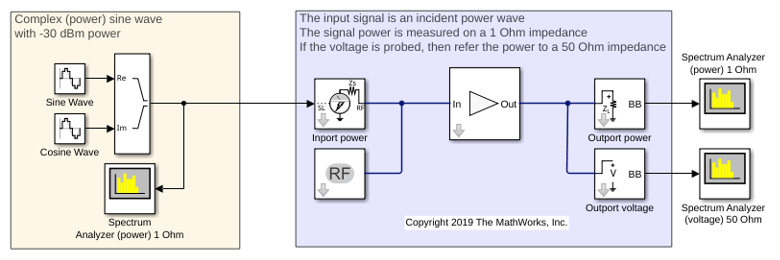
Power Ports and Signal Power Measurement in RF Blockset
Learn how to use power ports and measure the signal power in RF Blockset.
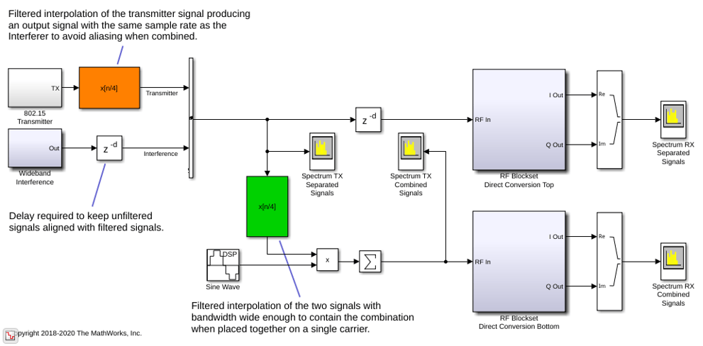
Automatic Sample-Time Interpolation at Input Port
Learn how to manage models consisting of both digital communication and RF systems that process signals at different sampling rates.

Communications System with Embedded RF Receiver
Learn how to integrate an RF receiver together with baseband signal processing algorithms to model an end-to-end communications system.

