Calculate Instantaneous Resistance in Equivalent Circuit Models
This topic shows how the fitECM function
calculates the instantaneous resistance in battery equivalent circuit models (ECM) to perform
impedance parameter estimation.
The instantaneous resistance in a battery equivalent circuit model (ECM) is a fundamental parameter that governs the immediate voltage response, limits the power output, affects the thermal behavior, and provides insight into the battery health. You must accurately estimate the instantaneous resistance to avoid undervoltage faults and provide safety in real-time battery applications.
The instantaneous resistance R0 of an equivalent circuit battery model is related to the ohmic resistance. The ohmic resistance originates from the phenomenon of electrical conduction in solid materials and, partially, in some electrolytes. Therefore, you can calculate the instantaneous resistance by using Ohm's law,
where:
ΔU is the voltage drop, in volts.
I is the current, in amperes.
R is the electrical resistance, in ohms.
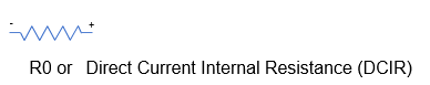
If you do not model any RC branches in the battery equivalent circuit, then R0 is called direct current internal resistance (DCIR). This table shows the distinction between R0 and DCIR. The instantaneous resistance is mainly a feature of RC equivalent circuit models.
| Circuit Name | Number of RC Pairs | Topology and Parameters |
|---|---|---|
| Single resistor | 0 |
|
| N-RC branch ECM | 1 - N |
|
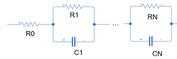
Unlike the instantaneous resistance R0, you can link the DCIR parameter to any number of timescales. For example, you can use Ohm's law to calculate the DCIR at two, five, 10, 30, and 60 seconds after you apply a constant current load to a battery cell:
where U0 is the initial voltage or
open-circuit voltage at the start of the pulse, in volts.
For RC-equivalent circuit models, the sampling frequency influences the calculation of the
instantaneous resistance. The fitECM function calculates the instantaneous
resistance by using this equation,
where:
UThresholdForR0 is the interpolated voltage at theThresholdForR0property value, in volts.IThresholdForR0 is the interpolated current at theThresholdForR0property value, in amperes.ThresholdForR0is the time at which to apply Ohm's law in seconds.
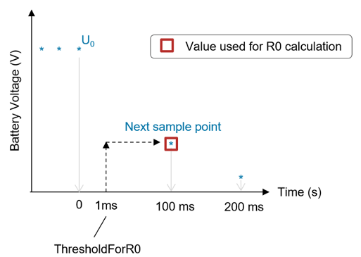
The function interpolates the voltage value at ThresholdForR0 using the
nearest interpolation and extrapolation:
This figure graphically shows the interpolation. In the figure, the
ThresholdForR0 value is 1 ms, but the fitECM function
uses the voltage and current values at 100 ms for the direct R0 equation. This is because the
interpolation is set to "nearest", so even if you specify a
ThresholdForR0 value, the calculation uses the nearest sample point, making
it dependent on the sampling frequency of the data.
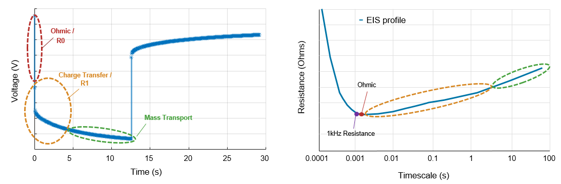
Electrochemical impedance spectroscopy (EIS) analysis of battery cells shows that the voltage drop due to the R0 or ohmic resistance is fully developed at a timescale of 1 to 10 milliseconds. As such, to accurately calculate the instantaneous (or ohmic) resistance, you must sample at this rate during the initial sections of a constant current pulse. These pulses are typically performed in test protocols like hybrid pulse power characterization (HPPC).
This figure shows a summary of the key impedance dynamics or overpotentials that occur and evolve over time when a battery is put under load. The left plot shows the measured voltage response of a battery to a constant current pulse. The voltage is measured as a function of time or pulse duration. The right plot shows the battery resistance as a function of the elapsed time under load.
The fitECM function performs impedance parameter estimation for a
battery ECM from time-based HPPC data. These parameters are then stored inside an
ECM object that you can use to parameterize a Battery Equivalent Circuit
block. For an example on how to estimate impedance parameters and how the
fitECM function calculates the instantaneous resistance, see Estimate Battery Model Parameters from HPPC Data.
You can select different fitting methods for estimating the model parameters. To choose the
fitting method and the segment of the pulse to fit, specify the
FittingMethod and SegmentToFit properties,
respectively. This table shows the list of available options for these properties in the
fitECM function. To select a method, you must have a license for any
associated MATLAB® toolboxes.
| Required MATLAB Toolboxes | FittingMethod Property | SegmentToFit Property |
|---|---|---|
| Simscape™ Battery™ | fminsearch |
|
| Simscape Battery and Curve Fitting Toolbox™ | curvefit |
|
| Simscape Battery and System Identification Toolbox™ | tfest |
|
| Simscape Battery and Model-Based Calibration Toolbox™ | mbc | Not Available |
The battery ECM parameters for a specific operating point can differ depending on which segment or section of the current pulse you use for the parameter estimation process. The load-segment parameters suit most applications. However, the best estimation segment depends on the specific end application of the battery ECM.
Some methods are better suited to estimate parameters for a given segment. For example, the
tfest function works best for fitting load-only dynamics. The
fminsearch method is very sensitive to initial parameter values, upper
parameter bounds, and lower parameter bounds.
The fitECM function calculates the ECM parameters in different ways
depending on the fitting method that you choose. For the
"fminsearch", "curvefit", and
"tfest" methods, the function uses the value of
ThresholdForR0 to directly calculate the ohmic resistance values based on
the initial voltage drop of the constant current pulse.
Calculate Instantaneous Resistance Using fminsearch method
When you select the fminsearch fitting method for the
fitECM function, the software calculates the parameters for a
discrete-time ECM by using the fminsearch function in Simscape
Battery.
Determine Average Pulse Current, Identify Order of Magnitude, and Detect Outliers
The function first calculates the average current during a pulse event. This current is essential for identifying the load and relaxation phases.
To calculate the average current during the pulse event, the fitECM
function computes the mean of the current values that exceed the value of the
CurrentOnThreshold argument. This threshold helps the function to
filter out the noise and focus on the actual
pulse.
meanPulseCurrent = mean(pulseData.Current(abs(pulseData.Current) > inputParameters.CurrentOnThreshold));
The function then determines the order of magnitude of the pulse current to better handle variations in current values.
pulseCurrentOrderMag = 10.^floor(log10(abs(meanPulseCurrent)));
To identify possible outliers, the function checks for large deviations in the current. The function compares the current values against a specific range. This range is the average current plus or minus a fraction of its order of magnitude.
hasOutlier = any((abs(meanPulseCurrent) + pulseCurrentOrderMag/5) <= abs(pulseData.Current(abs(pulseData.Current) > inputParameters.CurrentOnThreshold))) || ...
             any((abs(meanPulseCurrent) - pulseCurrentOrderMag/5) >= abs(pulseData.Current(abs(pulseData.Current) > inputParameters.CurrentOnThreshold)));
Identify End of Pulse
The function determines where the pulse ends based on the average current during the pulse event. If, in the previous step, the function identified outliers, it finds the last instance where the current is comparable to the mean pulse current. Otherwise, the function identifies the last point where the current exceeds the threshold.
if hasOutlier
    endOfPulseIndex = find(abs(meanPulseCurrent) <= abs(pulseData.Current), 1, 'last');
else
    endOfPulseIndex = find(abs(pulseData.Current) > inputParameters.CurrentOnThreshold, 1, "last");
end
Extract Load and Relaxation Segments
The function segments the data into load and relaxation phases based on the identified end of the pulse. The load phase represents the segment up to the end of the pulse. The relaxation phase represents the segment after the end of the pulse.
loadTime = seconds(pulseData.Time(1:endOfPulseIndex));
loadVoltage = pulseData.Voltage(1:endOfPulseIndex);
relaxationTime = seconds(pulseData.Time((endOfPulseIndex):end));
relaxationTime = relaxationTime - relaxationTime(1);
relaxationVoltage = pulseData.Voltage((endOfPulseIndex):end);
Calculate Instantaneous Resistance in Load and Relaxation Segments
The function calculates the instantaneous resistance for the load phase and the relaxation phase.
[loadOverpotential,loadOverpotentialForR0,loadR0] = calculateR0(loadTime, loadVoltage, inputParameters, inputParameters.CurrentAtR0Threshold);
[relaxOverpotential,relaxOverpotentialForR0,relaxR0] = calculateR0(relaxationTime, relaxationVoltage, inputParameters, inputParameters.PulseCurrent);
To calculate the instantaneous resistance, the calculateR0 function
first computes the instantaneous overpotential as the absolute difference between the pulse
voltage and the initial
voltage.
overpotential = abs(pulseVoltage - pulseVoltage(1));
The function then interpolates the voltage at the value of the
ThresholdForR0
argument.
overpotentialForR0 = interp1(pulseTime,overpotential,thresholdForR0,"nearest","extrap");
"nearest" input argument ensures that the interpolation
reflects the closest actual measurement. The "extrap" input
argument allows for consistent handling of points outside the time domain and enables
accurate R0 calculations even when the value of the
thresholdForR0 input argument is greater than the measured
interval.Finally, the function computes R0 from the overpotential and current. If the overpotential is zero, then the function uses the difference between the first two voltage measurements during the pulse. This calculation is a simple approximation of the initial voltage drop due to the internal resistance when the pulse begins. The function uses absolute values to calculate R0, so it returns a positive value of R0.
if overpotentialForR0 ~= 0
    R0 = abs(overpotentialForR0 / currentForR0);
else
    R0 = abs((pulseVoltage(2) - pulseVoltage(1))) / abs(currentForR0);
end
Handle Other Scenarios
The fitECM function also calculates R0 if the
pulse data does not fit the typical load and relaxation pattern, using a specified current
for the
calculation.
% Get pulse data.
pulseTime = seconds(pulseData.Time);
pulseVoltage = pulseData.Voltage;

% Calculate R0
if strcmp(inputParameters.SegmentToFit,"load")
    currentForR0 = inputParameters.CurrentAtR0Threshold;
else
    currentForR0 = inputParameters.PulseCurrent;
end
[overpotential,overpotentialForR0,R0] = calculateR0(pulseTime, pulseVoltage, inputParameters, currentForR0);
Calculate Instantaneous Resistance Using curvefit method
When you select the curvefit fitting method for the
fitECM function, the software calculates the parameters for a
discrete-time ECM by using the fit function in Curve Fitting Toolbox.
The calculation of the instantaneous resistance using the
curvefit fitting method follows the same first three steps as the
fminsearch fitting method. However, unlike the
fminsearch method, the curvefit
fitting method does not use the instantaneous overpotential.
The function calculates the instantaneous resistance for both load and relaxation phases.
[loadR0,loadInitialVoltage] = calculateR0(loadTime,loadVoltage,inputParameters,inputParameters.CurrentAtR0Threshold);
[relaxR0,relaxInitialVoltage] = calculateR0(relaxationTime,relaxationVoltage,inputParameters,inputParameters.PulseCurrent);
To calculate the instantaneous resistance, the calculateR0 function
first computes the initial voltage.
initialVoltage = pulseVoltage(1)
The function then interpolates the voltage at the value of the
ThresholdForR0
argument.
voltageForR0 = interp1(pulseTime,pulseVoltage,thresholdForR0,"nearest","extrap");
Finally, the function considers different scenarios for calculating R0. If the interpolated voltage does not match the initial voltage, the function uses the difference between the initial voltage and interpolated voltage.
if voltageForR0 ~= initialVoltage
    R0 = abs((voltageForR0-initialVoltage))/abs(currentForR0);
else
    R0 = abs((pulseVoltage(2)-pulseVoltage(1)))/abs(currentForR0);
end
Calculate Instantaneous Resistance Using tfest method
When you select the tfest fitting method for the
fitECM function, the software calculates the zeros and poles of a
transfer function by using the tfest function from System Identification Toolbox.
Detrend Voltage
The function removes the open-circuit voltage to isolate the dynamic response of the
battery, which is essential for accurate modeling. In this code,
pulseData is a timetable with a single unique timestep.
pulseData must contain only a single constant current pulse applied
to a lithium-ion
battery.
pulseVoltage = pulseData.Voltage - pulseData.OpenCircuitVoltage;
pulseCurrent = pulseData.Current;
Interpolate Voltage at R0 Threshold
To determine the instantaneous resistance, the fitECM function
must interpolate the voltage at the value of the ThresholdForR0
argument.
voltageForR0 = interp1(seconds(pulseData.Time),pulseVoltage,thresholdForR0,"nearest","extrap");
interp1 function to the detrended voltage
data.Calculate R0
Finally, the fitecm function considers different scenarios for
calculating R0. If the interpolated voltage does not match the initial voltage, the function
uses the difference between the initial voltage and the interpolated voltage. If the first
two voltage readings are identical, the function searches for the first differing value to
calculate R0, so that R0 is calculated even if the initial voltage readings are the
same.
if voltageForR0 ~= pulseVoltage(1)
    R0 = abs((voltageForR0 - pulseVoltage(1))) / abs(currentForR0);
elseif pulseVoltage(2) ~= pulseVoltage(1)
    R0 = abs((pulseVoltage(2) - pulseVoltage(1))) / abs(currentForR0);
else
    R0 = abs((pulseVoltage(find(pulseVoltage ~= pulseVoltage(1), 1, 'first')) - pulseVoltage(1))) / abs(currentForR0);
end