Ideal Rotational Motion Sensor
Sensores de movimiento en sistemas mecánicos de rotación
Bibliotecas:
Simscape /
Foundation Library /
Mechanical /
Mechanical Sensors
Descripción
El bloque Ideal Rotational Motion Sensor representa un sensor de movimiento mecánico de rotación ideal, es decir, un dispositivo que convierte una variable Across medida entre dos nodos mecánicos de rotación a una señal de control proporcional a la aceleración, la velocidad angular o la posición (ángulo). Puede especificar la posición angular inicial (desplazamiento) como un parámetro de bloque.
El sensor es ideal, puesto que no tiene en cuenta la inercia, la fricción, los retardos, el consumo de energía, etc.
Las conexiones R y C son puertos de transferencia mecánica de rotación que conectan el bloque a los nodos donde se supervisa el movimiento. La dirección positiva del bloque va del puerto R al puerto C, lo que significa que la velocidad se mide como ω = ωR – ωC, donde ωR y ωC son las velocidades angulares absolutas en los puertos R y C, respectivamente. El parámetro Measurement reference permite desactivar el puerto C y medir con respecto a la tierra.
Las conexiones α, W y A son puertos de salida de señal física para la aceleración angular, la velocidad y el desplazamiento, respectivamente. La visibilidad de estos puertos se controla con parámetros de bloque. Si activa el puerto α, el bloque realiza cálculos adicionales para medir la aceleración en función de la velocidad. Para evitar una complejidad innecesaria del modelo, es recomendable que en cada instancia del bloque solo active los puertos que realmente utilizará en la medición.
La casilla Wrap angle to [0, 2*pi] permite controlar el rango de salida del desplazamiento angular. Cuando está seleccionada, mantiene el desplazamiento angular dentro del rango de 0 a 2π radianes (360 grados), independientemente del número de revoluciones realizadas por el objeto y la dirección de rotación. Cuando se desactiva esta casilla, el rango de salida no tiene restricciones.
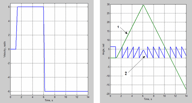
La figura muestra la diferencia entre ambas opciones.

En este ejemplo, el objeto se mueve a 6 rad/s en dirección positiva durante los 5 primeros segundos y, luego, cambia a la dirección negativa a la misma velocidad. La salida predeterminada del desplazamiento angular (línea 1) muestra que el objeto gira hacia delante 30 rad y, luego, gira hacia detrás en la dirección negativa, continuando hasta –20 rad. Si selecciona la casilla Wrap angle to [0, 2*pi], la salida (línea 2) permanece en el rango de 0 a 2π rad.
Si selecciona la casilla Wrap angle to [0, 2*pi], se simplifica el desarrollo de modelos con una relación compleja entre los parámetros del modelo y el ángulo de rotación, como bombas y motores.


