Main Content

Orientation

Measure device rotation along X, Y, and Z axes

Add-On Required: This feature requires the Simulink Support Package for Android Devices add-on.

  • Orientation block

Libraries:
Simulink Support Package for Android Devices / Sensors

Description

The Orientation block reads the rotation of the Android™ device. The rotation is measured using three angular quantities – Pitch (around X axis), Roll (around Y axis), and Azimuth (around Z axis). The block outputs the angles as a 1-by-3 vector in degrees.

During simulation without hardware, this block outputs zeros. For more information, see Block Produces Zeros or Does Nothing in Simulation.

This illustration shows the X, Y, and Z axes of a typical Android mobile phone. Each axis has an arrow which points in the positive direction.

Note

  • The coordinate system remains the same even when the device is moved.

  • The coordinate system is different for devices with different natural orientations. For example, the natural orientation of most Android mobile phones is portrait, and the natural orientation of most Android tablets is landscape. Therefore, the coordinate system of an Android tablet is different from the coordinate system shown in this illustration.

Examples

Ports

Output

expand all

The block outputs the rotation as a 1-by-3 vector. The vector elements represent the rotations in degrees along the X, Y, and Z axes of the Android device.

Data Types: single

Parameters

expand all

Specify how often the block reads rotation. When you specify this parameter as -1, Simulink® determines the best sample time for the block based on the block context within the model.

Read Orientation of Android Device

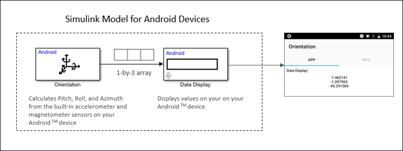
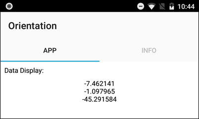
This Simulink model includes an Orientation block and a Data Display block. The Orientation block calculates Pitch, Roll, and Azimuth from the built-in accelerometer and magnetometer sensors on your Android device. The block outputs the rotation as a 1-by-3 vector. The Data Display block accepts the vector and displays the values on your Android device.

To run the model:

  1. Connect an Android device to your computer with a USB cable.

  2. Install the Simulink Support Package for Android Devices as described in Install Support for Android Devices.

  3. In the Modeling tab of the toolstrip, select Model Settings.

  4. In the Configuration Parameters dialog box, select Hardware Implementation.

  5. Set the Hardware board parameter to Android Device. This selection automatically populates the parameters in the Hardware board settings with the default values for Android.

  6. From the Groups list under Target hardware resources, select Device options.

  7. From the Device list, select your Android device. If your device is not listed, click Refresh.

    Note

    If your device is not listed even after clicking the Refresh button, ensure that you have enabled the USB debugging option on your device. To enable USB debugging, enter androidhwsetup in the MATLAB® Command Window and follow the onscreen instructions.

  8. Click Apply to save your changes. Click OK.

  9. On the Simulink editor toolbar, click the Build Model button . The model is loaded and starts running on the device. The orientation is displayed on the device screen. Move your Android device and observe the change in the values displayed on the screen.

More About

expand all

Version History

Introduced in R2018a