Design Custom Lamps
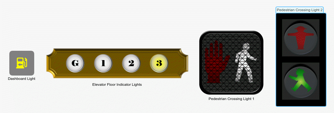
This example shows how to use the customizable Lamp block to design four lamps that look like displays in real systems:
A dashboard light in a passenger car
Elevator floor indicator lights
Two pedestrian crossing lights
Each lamp has multiple states. Each state corresponds to a value or a range of values that you specify. The lamp enters a given state when the value of the signal to which the Lamp block connects matches the specified value or falls within the specified range.
In each state, the lamp displays a combination of a shape layer and an icon layer. You can specify the appearance of a state by specifying the appearance of the layers for that state.
A Lamp block can also have a background image, a foreground image, or both. These do not change as the lamp switches states.
The blocks in the model use PNG images to define the shapes of these components. You can find all images used to create the lamps in the example directory.
Design Dashboard Light in Passenger Car
To design the dashboard light in a passenger car, add a customizable Lamp block to the model using the quick insert menu:
To open the quick insert menu, double-click in the canvas.
To search for the customizable Rocker Switch block, type
Lamp.Select the search result with the library path
Simulink/Dashboard/Customizable Blocks.
To modify the design of the Lamp block, enter design mode:
In the model canvas, select the Lamp block.
In the Simulink® Toolstrip, click the Lamp tab.
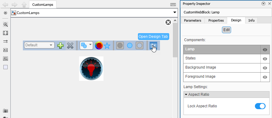
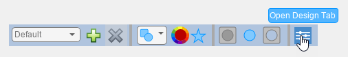
On the Lamp tab, click Edit. A toolbar appears above the Lamp block.
To open the Property Inspector, in the toolbar, click Open Design Tab. In design mode, the Design tab of the Property Inspector is active.
You can design a custom lamp using the toolbar or using the Design tab of the Property Inspector. This example uses both.
Change the background color to gray:
In the Property Inspector, on the Design tab, select the Background Image component.
In the Background Color section, turn on Use Background Color.
Change the Color to gray.

Delete the foreground image:
On the Design tab, select the Foreground Image component.
In the Select Image section, click the
Xbutton.

The Lamp block for the dashboard light has three states:
It is in the first state when the percent fuel left in the tank is between 0 and 30.
It is in the second state when the percent fuel left in the tank is between 30 and 100.
It is in the default state when the block does not receive a parameter value that activates any other of the specified states.
When the Lamp block is in the default state, the fuel icon on the car
dashboard is not lit.
Configure the appearance of the lamp for the default state:
On the Design tab, select the States component.
In the Icon section, open the drop-down menu and select
Automotive.Select the fuel icon.
In the toolbar, click the color wheel and set the color to black.
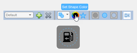
The toolbar color wheel sets the color of the shape layer of the lamp. Since the default Style setting in the Shape and Icon Combination section is Intersect, the lamp shows only the area of the shape layer that overlaps with the area of the icon layer. In this case, the shape layer is the circle that is selected in the Shape section, and the icon layer is the fuel symbol that is selected in the Icon section. Since the overlapping area is the shape of the fuel symbol, the toolbar color wheel changes the color of that symbol.
By default, states are activated by a single parameter value. However, the fuel symbol on the dashboard is lit when the percent fuel left is in a certain range, not when the percent fuel left is equal to a certain value. If you enable Specify State Values as Ranges, you can specify a range of values to activate each state.
Specify the range of parameter values that activate the second state:
In the Select State section, open the drop-down menu and select
1 (State 2). The number in this drop-down menu option is the parameter value that activates the state specified in parentheses.Turn on the Specify State Values as Ranges option. Observe that the drop-down menu option has changed from
1 (State 2)to1 to 1 (State 2). The numbers indicate the range of values that activate the state.In the Value and Color section, enter
100as the Maximum value of the range.In the Value and Color section, enter
30as the Minimum value of the range.
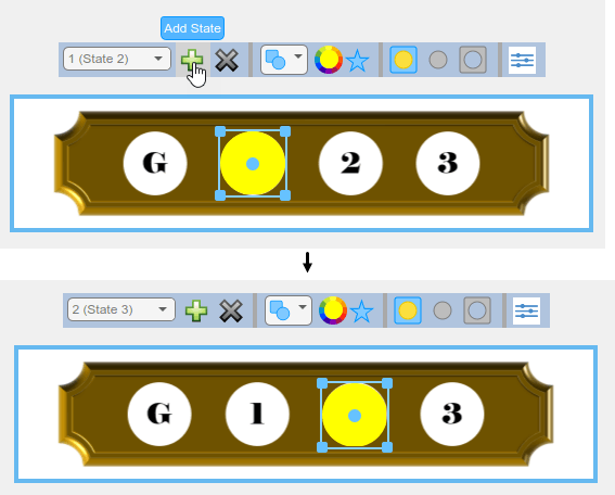
In the second state, the percent of fuel left in the tank is 30 to 100. The fuel icon on the car dashboard is not lit.
Configure the appearance of the lamp for the second state:
In the toolbar, click the color wheel and set the color for the icon layer to black.
![]()
Specify the range of parameter values that activate the first state:
On the Design tab of the Property Inspector, select the States component.
In the Select State section, open the drop-down menu and select
0 to 0 (State 1).In the Value and Color section, enter
30as the Maximum value of the range.
In the first state, the percent of fuel left in the tank is 0 to 30. The fuel icon on the car dashboard is lit.
Configure the appearance of the lamp for the first state:
In the toolbar, click the color wheel and set the color for the icon layer to yellow.
![]()
When you finish adjusting the design for the dashboard light, to exit design mode, on the Design tab, click Edit.
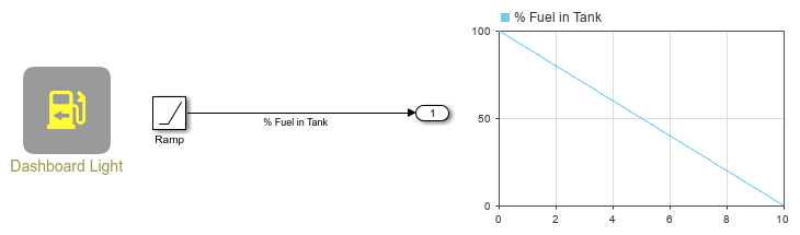
You can use the finished dashboard light to display a signal value. In the model, a Ramp block represents the percentage of fuel left in the tank of a car. The Ramp block has a slope of -10 and an initial output of 100.
Connect the Lamp block to the % Fuel in Tank signal:
Select the Lamp block.
Click the Connect button that appears above the block.
Select the signal line with the label
% Fuel in Tank.Select the
% Fuel in Tankoption in the table that appears below the selected signal line.Click the
Xin the upper right corner of the Simulink window.
To use the dashboard light, simulate the model. This model uses simulation pacing to slow model execution so that you can clearly see the Lamp block respond to the value of the parameter that it connects to. For more information about simulation pacing, see Simulation Pacing Options.
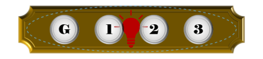
Design Elevator Floor Indicator Lights
To design a simple set of elevator floor indicator lights, add a customizable Lamp block to the model.
If the Property Inspector is not open to the Design tab with the Edit button pressed:
In the model canvas, select the Lamp block.
In the Simulink Toolstrip, click the Lamp tab.
On the Lamp tab, click Edit. A toolbar appears above the Lamp block.
To open the Property Inspector, in the toolbar, click Open Design Tab.
Add the background image for the floor indicator lights:
In the Property Inspector, on the Design tab, select the Background Image component.
In the Select Image section, click the plus button.
In the
CustomLampImagesfolder, select thefloor-indicator-background.pngfile.
Exit design mode by clicking Edit on the Design tab.
Resize the block in the canvas by dragging one of its corners outwards until the numbers on the background image are large enough to read.

To continue modifying the design of the Lamp block, enter design mode. In the Property Inspector, on the Design tab, click Edit.
Add the foreground image for the floor indicator lights:
On the Design tab, select the Foreground Image component.
In the Select Image section, click the plus button.
In the
CustomLampImagesfolder, select thefloor-indicator-foreground.pngfile.
Hide the foreground image so that it is not in the way when you configure the lamp appearance for each state. On the Design tab, click the eye icon of the Foreground Image component. The eye icon now has a slash through it, indicating that the foreground image is hidden.

Using the eye icon only hides the corresponding block component while you are in design mode. If you exit design mode, the component will become visible again.
The Lamp block for the floor indicator lights has five states:
It is in the first state when the elevator is on the ground floor, which corresponds to a parameter value of 0.
It is in the second state when the elevator is on the first floor, which corresponds to a parameter value of 1.
It is in the third state when the elevator is on the second floor, which corresponds to a parameter value of 2.
It is in the fourth state when the elevator is on the third floor, which corresponds to a parameter value of 3.
It is in the default state when the block does not receive a parameter value that activates any other of the specified states.
All states of the floor indicator lights have the same setting in the Shape and Icon Combination and Custom Icon sections. The Apply Default Settings to All States option is on. Configure the common settings for all states simultaneously by configuring them in the default state.
Configure all states to show the icon layer on top of the shape layer of the lamp:
On the Design tab, select the States component.
In the Shape and Icon Combination section, from Style, select
Simple.

To delete the custom icon for all states, in the Custom Icon section, click the X button.

For the floor indicator lights, the opacity of the shape layer of the lamp is also the same for all states. However, since the Apply Default Settings to All States option does not apply to the parameters in the Value and Color section, the remaining settings must be configured individually for each state.
In the Select State section, turn off the Apply Default Settings to All States option.
In the default state, all floor indicator lights are turned off.
In the Custom Icon section, set the Opacity to 0.

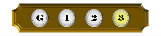
For each of the four non-default states, specify the parameter value that activates the state and configure the appearance of the lamp. In each state, the elevator reaches a different floor, and the corresponding floor indicator light turns yellow. To turn the light yellow, cover the labeled circle of the floor with a yellow circle.
For each non-default state:
In the Select State section, open the drop-down menu.
If the state is listed in the drop-down menu, select it. If not, click the plus button in the toolstrip to add a new state. Then, in the Select State section of the Property Inspector, select the new state from the drop-down menu.
To turn the shape layer of the light yellow, in the toolbar, click the color wheel and set the color to yellow.
To resize the surface, click and then drag one corner until the surface is the same size as the labeled circles on the background image. To maintain the aspect ratio of the surface, press Shift as you drag.
To position the surface, drag it on top of the labeled circle of the floor that the elevator reaches in the selected state.
To unhide the foreground image, on the Design tab, click the eye icon of the Foreground Image component. The eye icon no longer has a slash through it, indicating that the foreground image is visible again.
When you finish adjusting the design for the floor indicator lights, to exit design mode, on the Design tab, click Edit.
You can use the finished floor indicator lights to display a signal value. In the model, a From Workspace block represents the input signal to the floor indicator light panel.
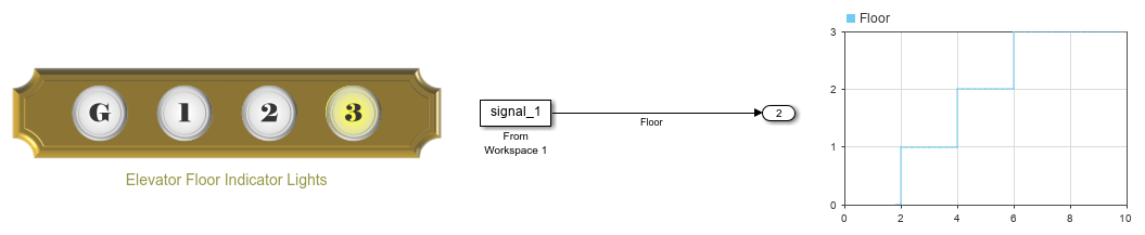
Connect the Lamp block to the Floor signal:
Select the Lamp block.
Click the Connect button that appears above the block.
Select the signal line with the label
Floor.Select the
Flooroption in the table that appears below the selected signal line.Click the
Xin the upper right corner of the Simulink window.
To use the floor indicator lights, simulate the model. This model uses simulation pacing to slow model execution so that you can clearly see the Lamp block respond to the value of the parameter that it connects to. For more information about simulation pacing, see Simulation Pacing Options.
Design Pedestrian Crossing Light Without Background Image
To design a pedestrian crossing light, add a customizable Lamp block to the model.
If the Property Inspector is not open to the Design tab with the Edit button pressed:
In the model canvas, select the Lamp block.
In the Simulink Toolstrip, click the Lamp tab.
On the Lamp tab, click Edit. A toolbar appears above the Lamp block.
To open the Property Inspector, in the toolbar, click Open Design Tab.
Delete the background image:
In the Property Inspector, on the Design tab, select the Background Image component.
In the Select Image section, click the
Xbutton.

Delete the foreground image:
On the Design tab, select the Foreground Image component.
In the Select Image section, click the
Xbutton.

Configure the states for the pedestrian crossing light. In the model, the crossing light is controlled by the walk light timer, which counts the elapsed seconds at the crosswalk for one minute, and then resets. Over the first half of that minute, the stop sign is on. Over the second half, the walk sign is on. The Lamp block represents this with three states:
It is in the first state when the value of the walk light timer signal is between 0 seconds and 30 seconds, the time range when pedestrians are not permitted to cross the street.
It is in the second state when the value of the walk light timer signal is between 30 seconds and 60 seconds, the time range when pedestrians are permitted to cross the street.
It is in the default state when the block does not receive a parameter value that activates any other of the specified states.
All states of the crossing light have the same settings in the Shape and Icon Combination and Size and Position sections. The Apply Default Settings to All States option is on. Configure the common settings for all states simultaneously by configuring them in the default state.
Configure all states to show the icon layer on top of the shape layer of the lamp:
On the Design tab, select the States component.
In the Shape and Icon Combination section, from Style, select
Simple.

To configure all states to maximize and center the icon within the area taken up by the block, in the Size and Position section:
Set the X Offset to
0.Set the Y Offset to
0.Set the Width to
1.Set the Height to
1.Set the Icon Size to
1.

For the crossing light, the opacity of the shape layer of the lamp is also the same for all states. However, since the Apply Default Settings to All States option does not apply to the parameters in the Value and Color section, the remaining settings must be configured individually for each state.
In the Select State section, turn off the Apply Default Settings to All States option.
In the default state, the crossing light is turned off. The Lamp block uses a custom icon to show this.
Configure the appearance of the lamp for the default state:
To render the shape layer of the lamp invisible, in the Value and Color section, set the set the Opacity to
0.To add the custom icon, in the Custom Icon section, click the plus button.
In the
CustomLampImagesfolder, select theped-xing-1-off.pngfile.

By default, states are activated by a single parameter value. However, the crosswalk light shows the walk signal over a certain time span, not at a certain time value. If you enable Specify State Values as Ranges, you can specify a range of values to activate each state.
Specify the range of parameter values that activate the second state:
In the Select State section, open the drop-down menu and select
1 (State 2). The number in this drop-down menu option is the parameter value that activates the state specified in parentheses.Turn on the Specify State Values as Ranges option. Observe that the drop-down menu option has changed from
1 (State 2)to1 to 1 (State 2). The numbers indicate the range of values that activate the state.In the Value and Color section, enter
60as the Maximum value of the range.In the Value and Color section, enter
30as the Minimum value of the range.
In the second state, the walk signal is lit. The Lamp block uses a custom icon to show the lit walk signal.
Configure the appearance of the lamp for the second state:
To render the shape layer of the lamp invisible, in the Value and Color section, set the set the Opacity to
0.To add the custom icon, in the Custom Icon section, click the plus button.
In the
CustomLampImagesfolder, select theped-xing-1-walk.pngfile.
![]()
Specify the range of parameter values that activate the first state:
On the Design tab of the Property Inspector, select the States component.
In the Select State section, open the drop-down menu and select
0 to 0 (State 1).In the Value and Color section, enter
30as the Maximum value of the range.
In the first state, the stop signal is lit. The Lamp block uses a custom icon to show the lit stop signal.
Configure the appearance of the lamp for the first state:
To render the shape layer of the lamp invisible, in the Value and Color section, set the set the Opacity to
0.To add the custom icon, in the Custom Icon section, click the plus button.
In the
CustomLampImagesfolder, select theped-xing-1-stop.pngfile.
![]()
Resize the block:
Exit design mode by clicking Edit on the Design tab.
In the canvas, drag one corner of the block outwards until the block is large enough to clearly show the crossing light symbols.
You can use the finished crossing light to display a signal value. In the model, a From Workspace block represents the walk light timer. The From Workspace block is set up such that one minute at the crosswalk corresponds to 2 seconds of simulation time. In the model, the crosswalk light therefore switches between stop and walk every second.
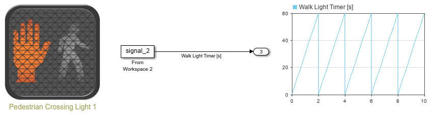
Connect the Lamp block to the Walk Light Timer [s] signal:
Select the Lamp block.
Click the Connect button that appears above the block.
Select the signal line with the label
Walk Light Timer [s].Select the
Walk Light Timer [s]option in the table that appears below the selected signal line.Click the
Xin the upper right corner of the Simulink window.
To use the crossing light, simulate the model. This model uses simulation pacing to slow model execution so that you can clearly see the Lamp block respond to the value of the parameter that it connects to. For more information about simulation pacing, see Simulation Pacing Options.
Design Pedestrian Crossing Light on Panel
If you want to design two lamps that share a common background but connect to different parameters, you can do so using panels.
To design a pedestrian crossing light with two lamps using this approach, add a customizable Lamp block to the model.
Configure this lamp to be the bottom lamp in the crossing light, which is the walk light.
If the Property Inspector is not open to the Design tab with the Edit button pressed:
In the model canvas, select the Lamp block.
In the Simulink Toolstrip, click the Lamp tab.
On the Lamp tab, click Edit. A toolbar appears above the Lamp block.
To open the Property Inspector, in the toolbar, click Open Design Tab.
Add the background image for the bottom lamp of the crossing light:
In the Property Inspector, on the Design tab, select the Background Image component.
In the Select Image section, click the plus button.
In the
CustomLampImagesfolder, select theped-xing-2-walk-off.pngfile.

Delete the foreground image:
On the Design tab, select the Foreground Image component.
In the Select Image section, click the
Xbutton.

Configure the states for the bottom lamp of the crossing light. In model, the bottom lamp in the crossing light is controlled by the walk light timer, which counts the elapsed seconds at the crosswalk for one minute, and then resets. Over the first half of that minute, the stop sign is on. Over the second half, the walk sign is on. The Lamp block represents this with three states:
It is in the first state when the value of the walk light timer signal is between 0 seconds and 30 seconds, the time range when pedestrians are not permitted to cross the street.
It is in the second state when the value of the walk light timer signal is between 30 seconds and 60 seconds, the time range when pedestrians are permitted to cross the street.
It is in the default state when the block does not receive a parameter value that activates any other of the specified states.
All states of the bottom lamp have the same settings in the Shape and Icon Combination and Size and Position sections. The Apply Default Settings to All States option is on. Configure the common settings for all states simultaneously by configuring them in the default state.
Configure all states to show the icon layer on top of the shape layer of the lamp:
On the Design tab, select the States component.
In the Shape and Icon Combination section, open the Style drop-down menu, and select
Simple.

To configure all states to maximize and center the icon within the area taken up by the block, in the Size and Position section:
Set the X Offset to
0.Set the Y Offset to
0.Set the Width to
1.Set the Height to
1.Set the Icon Size to
1.

For the bottom lamp, the opacity of the shape layer of the lamp is also the same for all states. However, since the Apply Default Settings to All States option does not apply to the parameters in the Value and Color section, the remaining settings must be configured individually for each state.
In the Select State section, turn off the Apply Default Settings to All States option.
In the default state, the bottom lamp is turned off. The Lamp block uses the background image to show the unlit walk signal.
Configure the appearance of the lamp for the default state:
In the Custom Icon section, click the
Xbutton.In the Value and Color section, set the Opacity to
0.

By default, states are activated by a single parameter value. However, the crosswalk light shows the walk signal over a certain time span, not at a certain time value. If you enable Specify State Values as Ranges, you can specify a range of values to activate each state.
Specify the range of parameter values that activate the second state:
In the Select State section, open the drop-down menu and select
1 (State 2). The number in this drop-down menu option is the parameter value that activates the state specified in parentheses.Turn on the Specify State Values as Ranges option. Observe that the drop-down menu option has changed from
1 (State 2)to1 to 1 (State 2). The numbers indicate the range of values that activate the state.In the Value and Color section, enter
60as the Maximum value of the range.In the Value and Color section, enter
30as the Minimum value of the range.
In the second state, the walk signal is lit. The Lamp block uses a custom icon to show the lit walk signal.
Configure the appearance of the lamp for the second state:
To render the shape layer of the lamp invisible, in the Value and Color section, set the set the Opacity to
0.To add the custom icon, in the Custom Icon section, click the plus button.
In the
CustomLampImagesfolder, select theped-xing-2-walk-on.pngfile.
![]()
Specify the range of parameter values that activate the first state:
On the Design tab of the Property Inspector, select the States component.
In the Select State section, open the drop-down menu and select
0 to 0 (State 1).In the Value and Color section, enter
30as the Maximum value of the range.
In the first state, the walk signal is not lit. The Lamp block uses the background image to show the unlit walk signal.
Configure the appearance of the lamp for the first state:
In the Custom Icon section, click the
Xbutton.In the Custom Icon section, set the Opacity to
0.
![]()
Exit design mode by clicking Edit on the Design tab.
Resize the block in the canvas by dragging one of its corners outwards until it is large enough to clearly show the walk symbol.

To configure the top lamp in the crossing light, copy and paste the Lamp block for the bottom lamp in the canvas. The copy represents the top lamp in the crossing light, which is the stop light.
To modify the design of the Lamp block, enter design mode:
On the Modeling tab, under Design, select Property Inspector.
In the model canvas, select the Lamp block.
In the Property Inspector, select the Design tab and click Edit.
Change the background image for the top lamp of the crossing light:
On the Design tab, select the Background Image component.
In the Select Image section, click the plus button.
In the
CustomLampImagesfolder, select theped-xing-2-stop-off.pngfile.

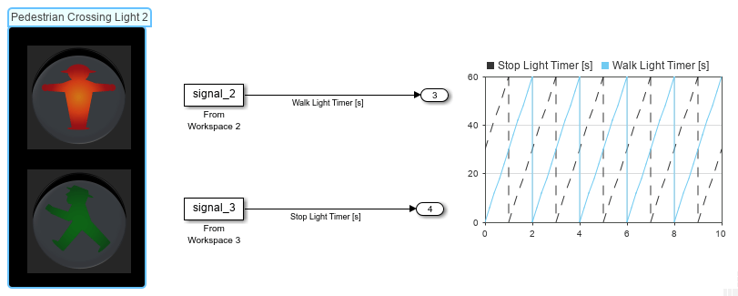
Configure the states for the top lamp of the crossing light. The top lamp is lit when the bottom lamp is off, and vice versa. In the model, the parameter value settings for the top lamp are the same as those for the bottom lamp, and the different timing of the two lamps is achieved by connecting the top lamp to a different timer, the stop light timer. This timer also counts the elapsed seconds at the crosswalk for one minute, and then resets. However, the signal of the stop light timer is offset from that of the walk light timer by 30 seconds.
Since both the top and bottom lamps of the crossing light have the same parameter value settings, you only need to configure the appearance of the top lamp for each state. Since the default state and the first state only show the background image, you do not need to modify these states.
In the second state, the stop signal is lit. The Lamp block uses a custom icon to show the lit stop signal.
Configure the appearance of the lamp for the second state:
To add the custom icon, in the Custom Icon section, click the plus button.
In the
CustomLampImagesfolder, select theped-xing-2-stop-on.pngfile.
![]()
Exit design mode by clicking Edit on the Design tab.
Select and drag the Lamp block of the top lamp, the stop signal, to be directly above the bottom lamp, the walk signal.

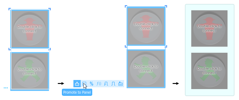
Promote both of the custom Lamp blocks for the crossing light to a panel:
Select both Lamp blocks in the canvas.
To open the action menu, click the three blue dots.
In the action menu, click the Promote to Panel button.
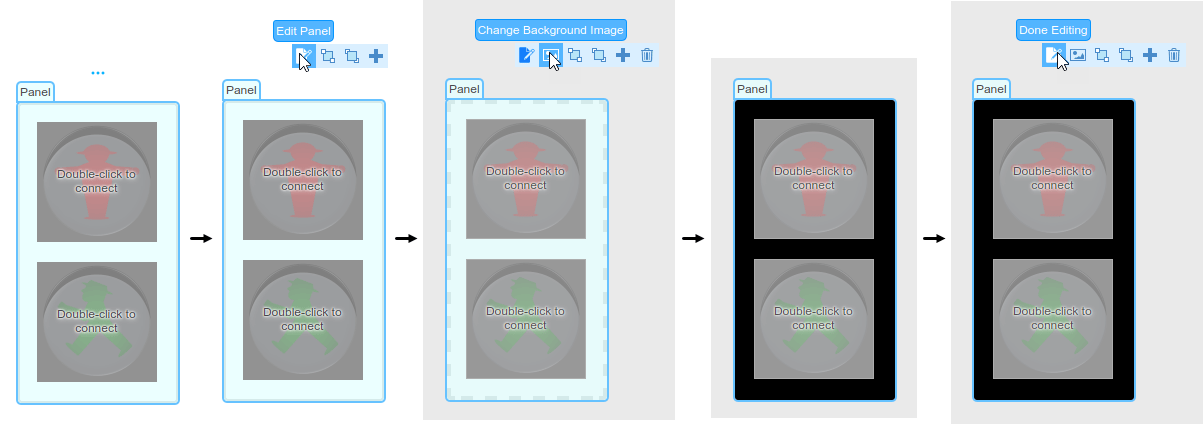
Change the background color of the panel to black:
Click the panel.
To open the action menu, click the three blue dots.
In the action menu, click the Edit Panel button.
In the action menu, click the Change Background Image button.
In the
CustomLampImagesfolder, select theped-xing-2-panel-background.pngfile.Click the panel. In the action menu, click the Done Editing button.
When you finish adjusting the design for the crossing light, to exit design mode, on the Design tab, click Edit.
You can use the finished crossing light to display a signal value. In the model, two From Workspace blocks represents the walk light and stop light timers. The From Workspace blocks are set up such that one minute at the crosswalk corresponds to 2 seconds of simulation time. In the model, the crosswalk light therefore switches between stop and walk every second.
Connect the bottom Lamp block to the Walk Light Timer [s] signal:
Select the Lamp block.
Click the Connect button that appears above the block.
Select the signal line with the label
Walk Light Timer [s].Select the
Walk Light Timeroption in the table that appears below the selected signal line.Click the
Xin the upper right corner of the Simulink window.
Connect the top Lamp block to the Stop Light Timer [s] signal:
Select the Lamp block.
Click the Connect button that appears above the block.
Select the signal line with the label
Stop Light Timer [s].Select the
Stop Light Timeroption in the table that appears below the selected signal line.Click the
Xin the upper right corner of the Simulink window.
To use the Pedestrian Crossing Light 2 Lamp blocks, simulate the model. This model uses simulation pacing to slow model execution so that you can clearly see the Lamp block respond to the value of the parameter that it connects to. For more information about simulation pacing, see Simulation Pacing Options.
The pedestrian crossing light you created in this example is on a panel. Note that panels float above the model canvas and do not zoom with the model. To minimize the panel, double-click the panel. To restore the panel, double-click the minimized panel. For more information on panels, see Getting Started with Dashboard Panels.