Reference Tracking of DC Motor with Parameter Variations
This example shows how to generate an array of LTI models that represent the plant variations of a control system from a Simulink® model. This array of models is used in Control System Designer for control design.
DC Motor Model
In armature-controlled DC motors, the applied voltage Va controls the angular velocity ![]() of the shaft. A simplified model of the DC motor is shown below.
of the shaft. A simplified model of the DC motor is shown below.
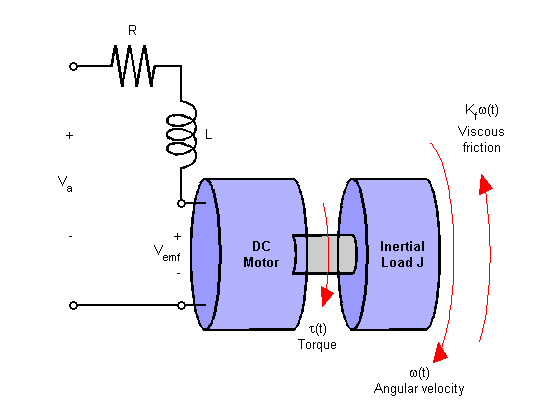
Open the Simulink model for the DC motor.
mdl = 'scdDCMotor';
open_system(mdl)
![]()
Perform Batch Linearization
The goal of the controller is to provide tracking to step changes in reference angular velocity.
For this example, the physical constants for the motor are:
R= 2.0 +/- 10% OhmsL= 0.5 HenrysKm= 0.1 Torque constantKb= 0.1 Back emf constantKf= 0.2 NmsJ= 0.02 +/- .01 kg m^2
Note that parameters R and J are specified as a range of values.
To design a controller which will work for all physical parameter values, create a representative set of plants by sampling these values.
For parameters R and J, use their nominal, minimum, and maximum values.
R = [2,1.8,2.2];
J = [.02,.03,.01];
To create an LTI array of plant models, batch linearize the DC motor plant. For each combination of the sample values of R and J, linearize the Simulink model. To do so, specify a linearization input point at the output of the controller block and a linearization output point with a loop opening at the output of the load block as shown in the model.
Get the linearization analysis points specified in the model.
io = getlinio(mdl);
Vary the plant parameters R and J.
[R_grid,J_grid] = ndgrid(R,J);
params(1).Name = 'R';
params(1).Value = R_grid;
params(2).Name = 'J';
params(2).Value = J_grid;
Linearize the model for each parameter value combination.
sys = linearize(mdl,io,params);
Open Control System Designer
Open Control System Designer, and import the array of plant models. using the following command.
controlSystemDesigner(sys)
Using Control System Designer, you can design a controller for the nominal plant model while simultaneously visualizing the effect on the other plant models as shown below.
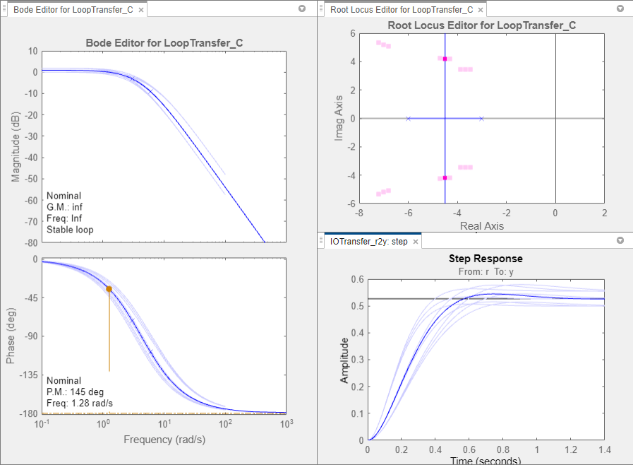
The root locus editor displays the root locus for the nominal model and the closed-loop pole locations associated with the other plant models.
The Bode editor displays both the nominal model response and the responses of the other plant models.
To view the step responses for all the plant models, right-click the Step Response plot and select Multimodel Display > Individual Responses. The step responses show that reference tracking is not achieved for any of the plant models.
Design Controller
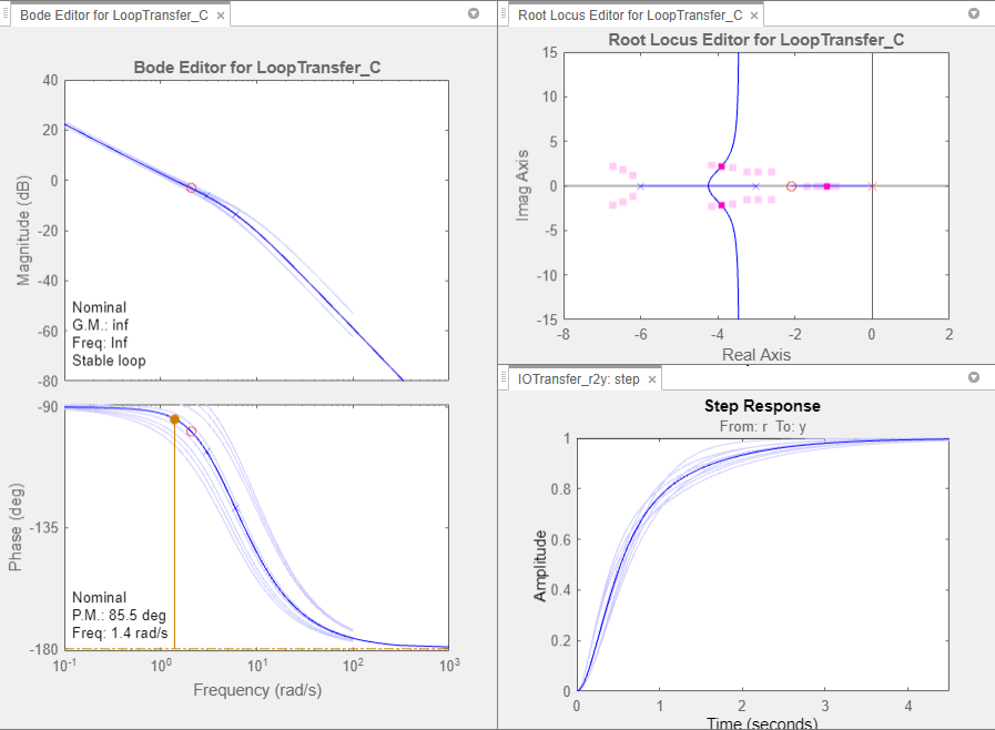
Using the tools in Control System Designer, design the following compensator for reference tracking.
![]()
The resulting design is shown below. The closed-loop step response shows that the goal of reference tracking is achieved with zero steady-state error for all models defined in the plant set. However, if a zero percent overshoot requirement is necessary, not all responses would satisfy this requirement.
Export Design and Validate in Simulink Model
To export the designed controller to the MATLAB® workspace, click Export. In the Export Model dialog box, select C, and click Export. Write the controller parameters to the Simulink model.
[Cnum,Cden] = tfdata(C,'v');
hws = get_param(mdl, 'modelworkspace');
assignin(hws,'Cnum',Cnum)
assignin(hws,'Cden',Cden)
More Information
For more information on using the multimodel features of Control System Designer, see Multimodel Control Design.