Extract Subsystems for Analysis
R2026bOverview of Subsystem Extraction
When you analyze an atomic subsystem or atomic subchart, the software:
Extracts the subsystem or subchart into a new model.
If required, adds blocks to the newly created model that replicate the execution context of the subsystem or subchart within its parent model.
Analyzes the extracted model and produces results.
Note
The Simulink® Design Verifier™ software can analyze only atomic subsystems and atomic subcharts. For more information about analyzing subsystems, see Generate Test Cases for a Subsystem. For more information about analyzing atomic subcharts, see Analyze a Stateflow Atomic Subchart.
Simulink Design Verifier does not support extraction of a Variant Subsystem block. For more information on Variant Subsystem block, see Variant Subsystem.
sldvextract Function
The sldvextract function
allows you to extract subsystems and atomic subcharts for component
verification. By extracting the subsystem or atomic subchart, you
can verify the component in isolation from the rest of the system,
allowing you to test the component algorithm. For more information,
see What Is Component Verification? and Functions for Component Verification.
Structure of the Extracted Model
When you analyze a subsystem or atomic subchart, Simulink Design Verifier creates a new model that contains the subsystem or atomic subchart, and any input and output ports that correspond to the ports connected to the original subsystem.
The software assigns the following properties to the ports in the new model, as determined by compiling the original model:
Data types
Sample rates
Signal dimensions
Minimum and maximum values of the signal ranges
The software names the new model subsystem_name, where
subsystem_name is the name of the subsystem.
The next sections provide examples of how Simulink Design Verifier extracts and analyzes subsystems.
Data Store Memory in Atomic Subsystems
A data store is a repository to which you can write data, and from which you can read data, without having to connect an input or output signal directly to the data store.
You create a data store by using a Data Store Memory block or a Simulink.Signal object. The Data Store Memory
block or Simulink.Signal object represents the data store and
specifies its properties. Every data store must have a unique name.
If you use sldvextract function on a subsystem which
references Data Store Memory blocks which are not defined within the
subsystem itself, Simulink
Design Verifier inserts corresponding Data Store Memory blocks into the
extracted model. Simulink
Design Verifier also inserts Data Store Write or Data Store
Read blocks and inports or outports into the extracted model depending
on the contents of the subsystem to be extracted. Consider the following example for
more detailed information.
A model contains a Data Store Memory block A, and a subsystem.
Using sldvextract function on this subsystem results in
different Simulink
Design Verifier behaviors depending on the contents of the subsystem:
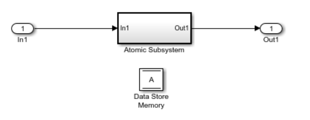
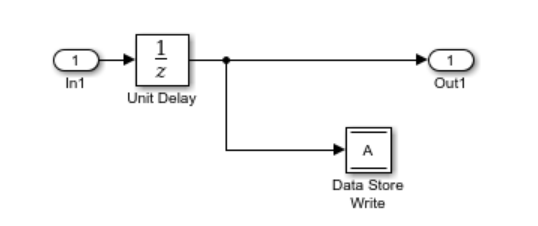
The subsystem to be extracted contains Data Store Read blocks, but does not contain any Data Store Write blocks.
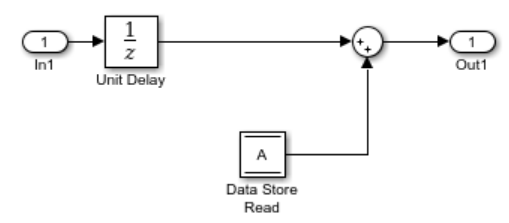
Simulink Design Verifier inserts corresponding Data Store Write blocks with inports into the extracted model.
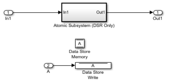
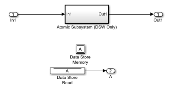
The subsystem to be extracted contains Data Store Write blocks, but does not contain any Data Store Read blocks.
Simulink Design Verifier inserts corresponding Data Store Read blocks with outports into the extracted model.
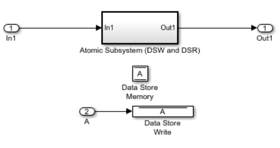
The subsystem to be extracted contains both Data Store Write and Data Store Read blocks.
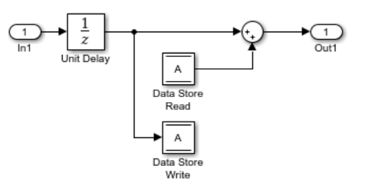
Simulink Design Verifier inserts corresponding Data Store Write blocks with inports into the extracted model.
Analyze Function-Call Subsystems
A function-call subsystem is a triggered subsystem whose execution is determined by logic internal to a C MEX S-function instead of by the value of a signal. Function-call subsystems are always atomic.
For more information, see Implement Function-Call Subsystems with S-Functions.
When you analyze a model with a function-call subsystem, Simulink® Design Verifier™ creates a new model with an Inport block that mimics the trigger and a copy of the subsystem. The software then analyzes the new model.
This example analyzes a function-call subsystem in the sl_subsys_fcncall2 model.
1. Open the sl_subsys_fcncall2 example model.
open_system('sl_subsys_fcncall2');2. This model contains a Stateflow® chart named Chart that triggers the function-call subsystem f.
Right-click the f subsystem. To add the Design Verifier app options to the menu, point to Select Apps and click the Design Verifier button  . Then, in the Design Verifier app section, select the Generate Tests for Subsystem click Generate Tests button
  .
.
The software extracts the subsystem into a new model named f0, analyzes the extracted model, and produces results.
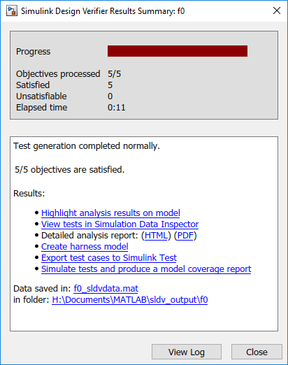
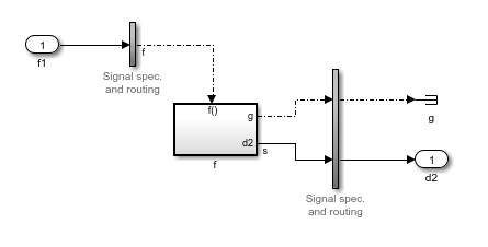
3. Open the f0 model that the software created in current_folder\sldv_output\f0.
The Inport block and the new subsystem block mimic the trigger for the function-call subsystem f in the new f0 model.
Analyze Global Simulink Function
A Simulink® function is a computational unit that calculates a set of outputs when provided with a set of inputs.
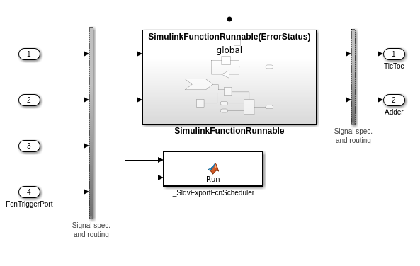
When you analyze Simulink Function subsystem, Simulink Design Verifier™ creates a new model containing a MATLAB® function block _SldvExportFcnScheduler and a copy of the subsystem. This MATLAB Function block invokes Simulink Functions aperiodically and is driven by inports which represent the input arguments of the Simulink Function. An additional Inport block called FcnTriggerPort, the value of which indicates whether to invoke a particular function in a time step or not.
The following example analyzes a global Simulink function in the sldvexGlobalSimFcn model.
1. Open the sldvexGlobalSimFcn model.
open_system('sldvexGlobalSimFcn');2. Right-click the subsystem and in the Design Verifier app section  , click the Generate Tests for Subsystem button
  .
.
The software extracts the subsystem into a new model and analyzes the extracted model, and produces results.
3. Open the new model SimulinkFunctionRunnable0 that the software creates in current_folder\sldv_output\.
The Inport block FcnTriggerPort, invokes the Simulink Function SimulinkFunctionRunnable in the new SimulinkFunctionRunnable0 model.