Generate Tests and Test Harnesses for a Model or Components
In the Test Manager, the Create Test for Component wizard creates a test harness and test case for a model or component in the model. You can also use the wizard to create test harnesses and test cases for multiple components in the model. Components for which you can create test harnesses include subsystems, Stateflow® charts, and Model blocks. For a full list of components supported by test harnesses, see Test Harness and Model Relationship. If you select a model component that is not compatible with the wizard, that component does not appear in the wizard.
In the wizard, you specify:
The model to test.
The component or components to test, if you are not testing a whole model.
The test inputs.
The type of test to run on the component.
Whether to save test data in a MAT file or Excel®. For more information on using Excel files in the Test Manager, see Input, Baseline, and Parameter Override Test Case Data Formats in Excel.
For an example that uses the wizard, see Back-to-Back Equivalence Testing.
Open the Create Test for Component Wizard
Before you run the wizard, check your model.
If you are testing the code for an atomic subsystem by using an equivalence test that uses software-in-the-loop (SIL) or processor-in-the-loop (PIL) mode, verify that the subsystem already has generated code.
If you are testing the code generated for a reusable library subsystem, before opening the Create Test for Component wizard, verify that the subsystem has defined function interfaces and that the library already has generated code. For information on reusable library subsystems, function interfaces, and generated code, see Library-Based Code Generation for Reusable Library Subsystems (Embedded Coder). You must have an Embedded Coder® license to verify generated code.
If you are testing one or more components, select the components in the model before opening the wizard. When the wizard opens, click Use currently selected components to add the selected components and fill in the Top Model field.
To open the Create Test for Component wizard, in the Test Manager select New > Test for Model Component.
Select Model or Component to Test

If you have not selected any components in the
model, on the first page of the wizard, click the Use current
model button ![]() to fill in the Top Model
field.
to fill in the Top Model
field.
Then, if you are testing:
A whole model, do not select add components to the Selected components pane.
To test the whole model without creating a test harness, clear Create Test Harness for component. If you are testing a specific component or components in the model, the wizard creates the test harnesses automatically, and the Create Test Harness for component option does not display.
One or more components and you did not select the components in the model before opening the wizard, select the component or press Ctrl and click the components to test. The click the plus button
 to add the components to the
Selected components pane. To remove one or more
components, press Ctrl and click to select them in
the Selected components pane, and click the remove
button
  .
.Component in a Model block, you do not need to specify the Model block as the top model. Use the name of the model that contains the Model block as the Top Model.
Reusable library subsystem that has a function interface, a Function Interface Settings option displays. Select the function interface for which you want to create a test. The Function Interface Settings option is not displayed if you select multiple components.

Reusable libraries contain components and subsystems that can be shared with multiple models. You can share the code generated by the subsystems if those subsystems are at the top level of the reusable library and if they have function interfaces. Function interfaces specify the subsystem input and output block parameter settings.
Note
For an export-function model, the test harness creates a Test Sequence block automatically.
If you have selected one or more components in the model, on the first page of the wizard, click Use currently selected components to fill in the Top Model field and add the selected components automatically.
Click Next to go to the next page of the wizard.
Set Up Test Inputs

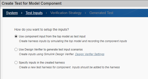
On the Test Inputs page, select how to obtain the test inputs.
Use component input from the top model as test input — Simulate the model and record the inputs to the component. Then, use those inputs as the inputs to the created test harness. Use this option for debugging.
Note
If you are testing a subsystem that has function calls, you cannot obtain inputs by simulating the model because function calls cannot be logged. Use either of the other two options to obtain the inputs.
Use Design Verifier to generate test input scenarios — Create test harness inputs to meet test coverage requirements using Simulink® Design Verifier™. This option appears only if Simulink Design Verifier is installed.
Simulate top model and use the recorded component inputs in the analysis — When coverage in test cases generated from Design Verifier is lower than expected, select this option to include top model simulation for the Design Verifier analysis.
Specify inputs in the created harness — After the wizard creates the harness, open the harness in the Test Manager and manually specify the harness inputs. This option does not appear if you chose not to create a test harness.
Test Method

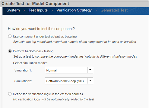
On the Verification Strategy page, select how to test the component.
Use component under test output as baseline — Simulate the model and record the outputs from the components, which are used as the baseline.
Perform back-to-back testing — Compare the results of running the component in two different simulation modes. For each simulation, select the mode from the drop-down menu. To conduct SIL testing on an atomic subsystem or a reusable library subsystem, the subsystem or library that contains the subsystem must already have generated code.
If you selected Use Design Verifier to generate test input scenarios on the Test Inputs tab, and you select Simulation2 to
Software-in-the-Loop (SIL)orProcessor-in-the-Loop (PIL), the wizard displays the Set Model Coverage Objective as Enhanced MCDC option. Enhanced MCDC extends MCDC coverage by generating test cases that avoid masking effects from downstream blocks. See Enhanced MCDC Coverage in Simulink Design Verifier (Simulink Design Verifier) and Create Back-to-Back Tests Using Enhanced MCDC (Simulink Design Verifier).Define the verification logic in the created harness — After the wizard creates the harness, open the harness. Manually specify the verification logic using a Test Sequence or Test Assessments block in the generated harness. Alternatively, use logical and temporal assessments or custom criteria in the generated test case. This option does not appear if you are testing a top-level model and choose not to create a test harness.
Save Test Data

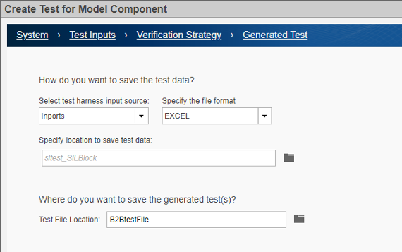
On the Generated Test page, select the format in which to save the test data and specify the filename for the generated tests.
Select test harness input source — Select how the inputs generated by the Design Verifier are applied to the test harness. This option appears only if you select Use Design Verifier to generate test input scenarios on the Test Inputs tab.
Inports— Create a test harness with Inport blocks as the source.Signal Editor— Create a test harness with the Signal Editor as the source that contains the input scenarios generated by the Design Verifier.
Specify the file format — Specify the type of file in which to save data. This option appears only if you select
Inportsas the input source.Excel— Saves the test inputs, outputs, and parameters to one sheet in an Excel spreadsheet file. For tests with multiple iterations, each iteration is in a separate sheet. For more information on using Excel files in the Test Manager, see Input, Baseline, and Parameter Override Test Case Data Formats in Excel.MAT— Saves inputs and outputs in separate MAT files. For tests that use Simulink Design Verifier, the wizard saves the inputs and parameters in one file and the outputs in a baseline file.
Specify location to save test data — Specify the full path of the file. Alternatively, you can use the default filename and location, which saves
sltest_<model name>in the current working folder. This option is available only for Excel format files. MAT files are saved to the default location specified in the model configuration settings.Test File Location — Specify the full path where you want to save the generated test files. Alternatively, you can use the default filename, which is
sltest_<model
                                name>_tests
. The file is saved in the current working folder. This field appears only if you did not have a test file open in the Test Manager before you opened the wizard.If you had a test file open in the Test Manager before you opened the wizard, these options are displayed instead of Test File Location:
Add tests to the currently selected test file — The generated tests are added to the test file that was selected in the Test Browser panel of the Test Manager when you opened the wizard.
Create a new test file containing the test(s) — A new test file is created for the tests. It appears in the Test Browser panel of the Test Manager.

Generate the Test Harness and Test Case
Click Done to generate a test harness and test case. A test harness is not created if you are testing a whole model and deselected Create a Test Harness on the first tab of the wizard.
The Test Manager then opens with the test case in the Test
Browser pane and, if a test harness was created, the test harness
name in the Harness field of the System Under
Test section. The test case is named <model
name>_Harness<#>.
Note
If the model has an existing external harness, the wizard creates an additional external test harness for the component under test. If no harness exists or if an internal harness exists, the wizard creates an internal test harness.
If you are testing the code for an atomic subsystem or model block using an
equivalence test and, on the Verification Strategy tab, you
set Simulation2 to Software-in-the-Loop
(SIL) or Processor-in-the-Loop (PIL), the
wizard creates only one test harness for both the normal and SIL or PIL
simulation modes. For other equivalence tests, the wizard creates two harnesses,
one for each simulation mode. For the following types of subsystems and model
configurations, the wizard creates two test harnesses, even if the subsystem is atomic.
Virtual subsystems
Function-call, For Each, If Action, S-Function, Initialize Function, Terminate Function, and Reset Function subsystems
Stateflow charts
Subsystems where the
ERTFilePackagingFormatproperty is set toCompactif the subsystem code has thePreserveStaticInFcnDeclsset toon.Subsystems that generate inline code, such as subsystems where the
RTWSystemCodeproperty is not eitherNonreusable functionorReusable function).Subsystems that contain referenced models, S-Function, Data Store Read, or Data Store Write blocks
Subsystems that have virtual buses at their interface
Subsystems that include LDRA or BullsEye code coverage
Subsystems that include signal logging
See Also
sltest.testmanager.createTestForComponent