Main Content

Three-Phase Transformer (Two Windings)

Implement three-phase transformer with configurable winding connections

  • Three-Phase Transformer (Two Windings) block

Libraries:
Simscape / Electrical / Specialized Power Systems / Power Grid Elements

Description

This block implements a three-phase transformer using three single-phase transformers. For a detailed description of the electrical model of a single-phase transformer, see the Linear Transformer block.

When activated, the saturation characteristic is the same as the one described for the Saturable Transformer block. If the fluxes are not specified, the initial values are automatically adjusted so that the simulation starts in steady state.

The leakage inductance and resistance of each winding are given in pu based on the transformer nominal power Pn and on the nominal voltage of the winding (V1 or V2). For a description of per units, refer to the Linear Transformer and to the Saturable Transformer.

The two windings of the transformer can be connected as follows:

  • Y

  • Y with accessible neutral

  • Grounded Y

  • Delta (D1), delta lagging Y by 30 degrees

  • Delta (D11), delta leading Y by 30 degrees

If you select the Y connection with accessible neutral for winding 1, an input port labeled N is added to the block. If you ask for an accessible neutral on winding 2, an extra output port labeled n is generated.

The D1 and D11 notations refer to the clock convention that assumes that the reference Y voltage phasor is at noon (12) on a clock display. D1 and D11 refer respectively to 1:00 p.m. (delta voltages lagging Y voltages by 30 degrees) and 11:00 a.m. (delta voltages leading Y voltages by 30 degrees).

Standard Notation for Winding Connections

The conventional notation for a two-winding three-phase transformer uses two letters followed by a number. The first letter (Y or D) indicates a high-voltage wye or delta winding connection. The second letter (y or d) indicates a low-voltage wye or delta winding connection. The number, an integer between 0 and 12, indicates the position of the low-voltage positive-sequence voltage phasor on a clock display when the high-voltage positive-sequence voltage phasor is at 12:00.

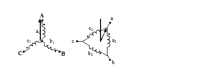
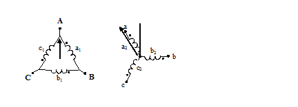
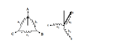
The following three figures are examples of standard winding connections. The dots indicate polarity marks, and arrows indicate the position of phase A-to-neutral voltage phasors on high-voltage and low-voltage windings. The phasors are assumed to rotate in a counterclockwise direction so that rising numbers indicate increasing phase lag.

  • Yd1: The low-voltage winding (d) is lagging high-voltage winding (Y) by 30 degrees. The Winding 2 connection parameter is set to D1.
  • Dy11: The low-voltage winding (y) is leading high-voltage winding (D) by 30 degrees. The Winding 1 connection parameter is set to D1.
  • Dy1: The low-voltage winding (y) is lagging high-voltage winding (D) by 30 degrees. The Winding 1 connection parameter is set to D11.
You can represent many other connections with phase shifts between 0 and 360 degrees (by steps of 30 degrees) by combining the +30- or –30-degree phase shift provided by the D1 and D11 block parameter settings and, in some cases, an additional +/–120-degree phase shift obtained by connecting the output terminals of delta winding to the appropriate phases of the network.

The table explains how to set up the Three-Phase Transformer block to obtain common connections.

Clock PositionPhase Shift (degrees)ConnectionWinding 1 ConnectionWinding 2 ConnectionTerminals of Delta Winding to Connect to Network ABC Phases
00Yy0YY
Dd0D1D1abc
1–30Yd1YD1abc
Dy1D11Yabc
2–60Dd2D11D1abc
5–150Yd5YD1bca
Dy5D11Ycab
7+150Yd7YD11cab
Dy7D1Ybca
10+60Dd10D1D11abc
11+30Yd11YD11abc
Dy11D1Yabc

For example, to obtain the Yd5 connection, set the Winding 1 connection parameter to Y and the Winding 2 connection parameter to D1, and connect the network phases to the winding 2 as follows:

For more details on conventional transformer winding notations, see International Standard IEC 60076-1 [1].

Examples

The power_transfo3ph circuit uses the Three-Phase Transformer block where the saturable core is simulated. Both windings are connected in a Y grounded configuration. The neutral points of the two windings are internally connected to the ground.

The 500 kV/ 230-kV saturable transformer is energized on the 500-kV system. Remanent fluxes of 0.8 pu, −0.4 pu, and 0.4 pu have been specified respectively for phases A, B, and C. Run the simulation and observe inrush currents due to core saturation. See also the power_xfonotation model that shows four types of three-phase Yd and Dy transformer connections.

Ports

Conserving

expand all

Electrical conserving port associated with the phase A terminal of winding 1.

Electrical conserving port associated with the phase B terminal of winding 1.

Electrical conserving port associated with the phase C terminal of winding 1.

Electrical conserving port associated with the neutral terminal of winding 1.

Dependencies

To enable this port, set the Winding 1 connection (ABC terminals) parameter to Yn.

Electrical conserving port associated with the phase A terminal of winding 2.

Electrical conserving port associated with the phase B terminal of winding 2.

Electrical conserving port associated with the phase C terminal of winding 2.

Electrical conserving port associated with the neutral terminal of winding 2.

Dependencies

To enable this port, set the Winding 2 connection (abc terminals) parameter to Yn.

Parameters

expand all

To edit block parameters interactively, use the Property Inspector. From the Simulink® Toolstrip, on the Simulation tab, in the Prepare gallery, select Property Inspector.

Configuration

Winding connections for winding 1. Choices are Y, Yn, Yg (default), Delta (D1), and Delta (D3).

Winding connections for winding 2. Choices are Y, Yn, Yg (default), Delta (D1), and Delta (D11).

Select Three single-phase transformers (default) to implement a three-phase transformer using three single-phase transformer models. You can use this core type to represent very large power transformers found in utility grids (hundreds of MW).

Select Three-limb core (core-type) to implement a three-limb core three-phase transformer. In most applications, three-phase transformers use a three-limb core (core-type transformer). This type of core produces accurate results during an asymmetrical fault for both linear and nonlinear models (including saturation). During asymmetrical voltage conditions, the zero-sequence flux of a core-type transformer returns outside the core, through an air gap, structural steel, and a tank. Thus, the natural zero-sequence inductance L0 (without delta winding) of such a core-type transformer is usually very low (typically 0.5 pu < L0 < 2 pu) compared with a three-phase transformer using three single-phase units (L0 > 100 pu). This low L0 value affects voltages, currents, and flux unbalances during linear and saturated operation.

Select Five-limb core (shell-type) to implement a five-limb core three-phase transformer. On rare occasions, very large transformers are built with a five-leg core (three phase legs and two external legs). This core configuration, also known as shell type, is chosen mainly to reduce the height of the transformer and make transportation easier. During unbalanced voltage conditions, as opposed to the three-limb transformer, the zero-sequence flux of the five-limb transformer stays inside the steel core and returns through the two external limbs. The natural zero-sequence inductance (without delta) is therefore very high (L0 > 100 pu). Except for small current unbalances due to core asymmetry, the behavior of the five-limb shell-type transformer is similar to that of a three-phase transformer built with three single-phase units.

If selected, implements a saturable three-phase transformer. Default is cleared.

If you want to simulate the transformer in the phasor mode of the Powergui block, you must clear this parameter.

Select to model a saturation characteristic including hysteresis instead of a single-valued saturation curve.

If you want to simulate the transformer in the phasor mode of the Powergui block, you must clear this parameter.

Dependencies

To enable this parameter, select the Simulate saturation parameter.

Specify a .mat file containing the data for use in the hysteresis model. When you open the Hysteresis Design Tool of the Powergui block, the default hysteresis loop and parameters saved in the hysteresis.mat file are displayed. Use the Load button of the Hysteresis Design tool to load another .mat file. Use the Save button of the Hysteresis Design tool to save your model in a new .mat file.

Dependencies

To enable this parameter, select the Simulate hysteresis parameter.

If selected, the initial fluxes are defined by the Initial fluxes parameter on the Parameters tab.

When the Specify initial fluxes parameter is not selected upon simulation, Simscape™ Electrical™ Specialized Power Systems software automatically computes the initial fluxes to start the simulation in steady state. The computed values are saved in the Initial Fluxes parameter and will overwrite any previous values.

Dependencies

To enable this parameter, select the Simulate saturation parameter.

Select Winding voltages to measure the voltage across the winding terminals.

Select Winding currents to measure the current flowing through the windings.

Select Fluxes and excitation currents (Im + IRm) to measure the flux linkage, in volt seconds (V.s), and the total excitation current including iron losses modeled by Rm.

Select Fluxes and magnetization currents (Im) to measure the flux linkage, in volt seconds (V.s), and the magnetization current, in amperes (A), not including iron losses modeled by Rm.

Select All measurements (V, I, Flux) to measure the winding voltages, currents, magnetization currents, and the flux linkages.

Place a Multimeter block in your model to display the selected measurements during the simulation. In the Available Measurements list box of the Multimeter block, the measurements are identified by a label followed by the block name.

If the Winding 1 connection (ABC terminals) parameter is set to Y, Yn, or Yg, the labels are as follows.

Measurement

Label

Winding 1 voltages

Uan_w1:

or

Uag_w1:

Winding 1 currents

Ian_w1:

or

Iag_w1:

Fluxes

Flux_A:

Magnetization currents

Imag_A:

Excitation currents

Iexc_A:

The same labels apply for winding 2, except that 1 is replaced by 2 in the labels.

If the Winding 1 connection (ABC terminals) parameter is set to Delta (D1) or Delta (D3), the labels are as follows.

Measurement

Label

Winding 1 voltages

Uab_w1:

Winding 1 currents

Iab_w1:

Flux linkages

Flux_A:

Magnetization currents

Imag_A:

Excitation currents

Iexc_A:

Parameters

Specify the units used to enter the parameters of this block. Select pu to use per unit. Select SI to use SI units. Changing the Units parameter from pu to SI, or from SI to pu, automatically converts the parameters displayed in the mask of the block. The per unit conversion is based on the transformer rated power Pn in VA, nominal frequency fn in Hz, and nominal voltage Vn, in Vrms, of the windings.

Nominal power rating, in volt-amperes (VA), and nominal frequency, in hertz (Hz), of the transformer. The nominal parameters have no impact on the transformer model when the Units parameter is set to SI.

Phase-to-phase nominal voltage in volts RMS, resistance, and leakage inductance in pu for winding 1. Default is [ 735e3 , 0.002 , 0.08 ] when the Units parameter is pu and [7.35e+05 4.3218 0.45856] when the Units parameter is SI.

Phase-to-phase nominal voltage in volts RMS, resistance, and leakage inductance in pu for winding 2. Default is [ 315e3 , 0.002 , 0.08 ] when the Units parameter is pu and [3.15e+05 0.7938 0.084225] when the Units parameter is SI.

Magnetization resistance Rm, in pu. Default is 500 when the Units parameter is pu and 1.0805e+06 when the Units parameter is SI.

Magnetization inductance Lm, in pu, for a nonsaturable core. Default is 500 when the Units parameter is pu and 2866 when the Units parameter is SI.

Dependencies

To enable this parameter, clear the Saturable core parameter.

The Inductance L0 of zero-sequence flux path return, in pu, for the three-limb core transformer type.

Default is 0.5 when the Units parameter is pu and 2.866 when the Units parameter is SI.

Dependencies

To enable this parameter, set Type to Three-limb core (core type).

Saturation characteristic. Default is [ 0,0 ; 0.0024,1.2 ; 1.0,1.52 ] when the Units parameter is pu and [0 0;0.66653 1910.3;277.72 2419.7] when the Units parameter is SI.

The saturation characteristic for the saturable core. Specify a series of current/ flux pairs (in pu) starting with the pair (0,0).

Dependencies

To enable this parameter, select the Simulate saturation parameter.

Specify initial fluxes for each phase of the transformer. Default is [ 0.8 , -0.8 , 0.7 ] when the Units parameter is pu and [1273.5 -1273.5 1114.3] when the Units parameter is SI.

When the Specify initial fluxes parameter is not selected upon simulation, Simscape Electrical Specialized Power Systems software automatically computes the initial fluxes to start the simulation in steady state. The computed values are saved in the Initial Fluxes parameter and overwrite any previous values.

Dependencies

To enable this parameter, select the Specify initial fluxes and Simulate saturation parameters.

Advanced

The Advanced tab of the block is not visible when you set the Simulation type parameter of the powergui block to Continuous, or when you select the Automatically handle discrete solver parameter of the powergui block. The tab is visible when you set the Simulation type parameter of the powergui block to Discrete, and when the Automatically handle discrete solver parameter of the powergui block is cleared.

When selected, a delay is inserted at the output of the saturation model computing magnetization current as a function of flux linkage (the integral of input voltage computed by a Trapezoidal method). This delay eliminates the algebraic loop resulting from trapezoidal discretization methods and speeds up the simulation of the model. However, this delay introduces a one simulation step time delay in the model and can cause numerical oscillations if the sample time is too large. The algebraic loop is required in most cases to get an accurate solution.

When cleared (default), the Discrete solver model parameter specifies the discretization method of the saturation model.

Select one of these methods to resolve the algebraic loop.

  • Trapezoidal iterative—Although this method produces correct results, it is not recommended because Simulink tends to slow down and may fail to converge (simulation stops), especially when the number of saturable transformers is increased. Also, because of the Simulink algebraic loop constraint, this method cannot be used in real time. In R2018b and previous releases, you used this method when the Break Algebraic loop in discrete saturation model parameter was cleared.

  • Trapezoidal robust—This method is slightly more accurate than the Backward Euler robust method. However, it may produce slightly damped numerical oscillations on transformer voltages when the transformer is at no load.

  • Backward Euler robust—This method provides good accuracy and prevents oscillations when the transformer is at no load.

The maximum number of iterations for the robust methods is specified in the Preferences tab of the powergui block, in the Solver details for nonlinear elements section. For real time applications, you may need to limit the number of iterations. Usually, limiting the number of iterations to 2 produces acceptable results. The two robust solvers are the recommended methods for discretizing the saturation model of the transformer.

For more information on what method to use in your application, see Simulating Discretized Electrical Systems.

References

[1] IEC. International Standard IEC 60076-1, Power Transformer - Part 1: General, Edition 2.1, 2000–04. "Annex D: Three-phase transformer connections." 2000.

Extended Capabilities

C/C++ Code Generation
Generate C and C++ code using Simulink® Coder™.

Version History

Introduced before R2006a

Go to top of page