Robótica y mecatrónica
Utilice estos ejemplos para aprender a controlar motores, comparar características y desarrollar actuadores eléctricos.
Ejemplos destacados

Brushless DC Motor
How a system-level model of a brushless DC motor (i.e. a servomotor) can be constructed and parameterized based on datasheet information. The motor and driver are modeled as a single masked subsystem. If viewing the model in Simulink®, select the Motor and driver block, and type Ctrl+U to look under the mask and see the model structure.

Compound Motor Design Optimization
Find design parameters that optimize a compound motor torque-speed curve to match the desired curve.
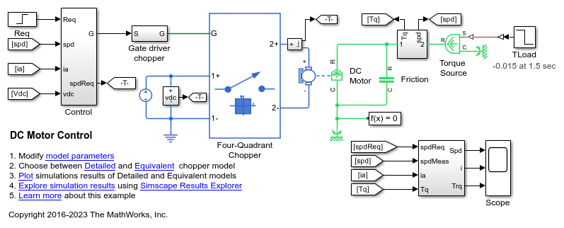
Control de motores de CC
Este ejemplo muestra una estructura de control de velocidad en cascada para un motor de CC. Se utiliza un seccionador de cuatro cuadrantes controlado por PWM para alimentar al motor de CC. El subsistema Control incluye el bucle de control de velocidad externo, el bucle de control de corriente interno y la generación de PWM. El tiempo total de simulación (t) es 4 segundos. En el instante t= 1,5 segundos, el par motor de la carga aumenta. En el instante t= 2,5 segundos, la velocidad de referencia cambia de 1.000 rpm a 2.000 rpm.

DC Motor Control (Lead-Lag)
A lead-lag speed-control structure for a DC motor. A PWM controlled four-quadrant Chopper is used to feed the DC motor. The Control subsystem includes a lead-lag controller, a constant gain, and the PWM generation. The total simulation time (t) is 4 seconds. At t = 1.5 seconds, the load torque increases. At t = 2.5 seconds, the reference speed is changed from 1000 rpm to 2000 rpm.

DC Motor Control (RST)
An RST speed-control structure for a DC motor. A PWM controlled four-quadrant Chopper is used to feed the DC motor. The Control subsystem includes the RST controller with control horizon of 30, and the PWM generation. A sensor measures the rotor speed with a delay of 5ms. The total simulation time (t) is 4 seconds. At t = 1.5 seconds, the load torque increases. At t = 2.5 seconds, the reference speed is changed from 1000 rpm to 2000 rpm.

DC Motor Control (Smith Predictor)
A Smith Predictor speed-control structure for a DC motor. A PWM controlled four-quadrant Chopper is used to feed the DC motor. The Control subsystem includes the Smith predictor controller, and the PWM generation. A sensor measures the rotor speed with a delay of 5ms. The total simulation time (t) is 4 seconds. At t = 1.5 seconds, the load torque increases. At t = 2.5 seconds, the reference speed is changed from 1000 rpm to 2000 rpm.

DC Motor Control (State-Feedback and Observer)
A state-feedback speed-control structure for a DC motor. A PWM controlled four-quadrant Chopper is used to feed the DC motor. The Control subsystem includes the state-feedback control loop, and the PWM generation. The state vector includes the rotor speed which is measured, and the dc motor current, which is estimated using an observer. Both the observer and state-feedback controller are synthesized by pole placement using the state-space model of the system. The total simulation time (t) is 4 seconds. At t = 1.5 seconds, the load torque increases. At t = 2.5 seconds, the reference speed is changed from 1000 rpm to 2000 rpm.

Hybrid Linear Actuator
A hybrid actuator consisting of a DC motor plus lead screw in series with a piezoelectric stack. The DC motor and lead screw combination supports large displacements (tens of millimeters), but is dynamically slow when tracking the reference demand x_ref. Conversely the piezoelectric stack only supports a maximum displacement of +-0.1mm, but has a very fast dynamic response. Combining the two actuator technologies creates a large stroke actuator with highly precise positioning.

Import Efficiency Map Data from Motor-CAD
Import efficiency map data from Motor-CAD to parameterize the Simscape™ Electrical™ Motor & Drive (System Level) block. This provides fast system-level simulation capability of a motor drive whilst still making accurate predictions about losses.

Linear Electric Actuator (Motor Model)
How to develop a model of an uncontrolled linear actuator using datasheet parameter values. The actuator consists of a DC motor driving a 6.25:1 worm gear which in turn drives a 3mm lead screw to produce linear motion. Manufacturer data for the actuator defines the no-load linear speed (26mm/s), rated load (1000N), rated-load linear speed (19mm/s), and maximum current (5A). The maximum static force is 4000N and the rated voltage is 24V DC.

Linear Electric Actuator with Control
A detailed implementation model of a controlled linear actuator. The actuator consists of a DC motor driving a worm gear which in turn drives a lead screw to produce linear motion. The model includes quantization effects of the Hall-effect sensor and the implementation of the control in analog electronics. There are multiple variant subsystems in this model that have models at varying levels of fidelity.

Model a Motor Drive with Multiple Intermittent Torque Limits
Model a motor drive with multiple intermittent over-torque limits by using Simscape™ Electrical™.

Motor Torque-Speed Curves
A comparison of the torque-speed characteristics for five different motor types. To select the motor type, right-click on the Electric Motor block and select Block Parameters (Subsystem) from the context menu. In the new window, specify the desired motor using the Label mode active choice parameter. All motors have been sized for roughly the same mechanical power rating.

Controlar motores de CC con fuente de tensión PWM y controlador de puente en H
Este ejemplo muestra cómo controlar un motor de CC utilizando los bloques Controlled PWM Voltage y H-Bridge. El bloque DC Motor proporciona una potencia mecánica de 10 W a 2.500 rpm y gira a una velocidad sin carga de 4.000 rpm cuando la tensión de alimentación de CC es 12 V. En consecuencia, si establece la tensión de referencia PWM en su valor máximo de 5 V, el motor funciona a 4.000 rpm. Si establece la tensión de referencia PWM en 2,5 V, el motor funciona a aproximadamente 2.000 rpm. Para lograr una simulación rápida, este ejemplo establece el parámetro Simulation mode de los bloques Controlled PWM Voltage y H-Bridge en Averaged. Para validar el comportamiento promediado, establezca el parámetro Simulation mode en PWM en los bloques Controlled PWM Voltage y H-Bridge.

Stepper Motor Averaged Mode
The Stepper Motor simulating in Stepping and Averaged simulation modes. The purpose of Averaged mode is faster simulation for any loads that do not cause slip. To avoid incorrect interpretation of results, the stepper motor has an approximate detection of slip which can be set to generate a warning or an error.

Stepper Motor with Control
Model a controlled permanent magnet stepper motor by using the Stepper Motor and Stepper Motor Driver blocks. The model has two controller options: one to control position and one to control speed. To change the controller type, right-click the Controller subsystem, select Variant > Label Mode Active Choice, and then select Position or Speed. The stepper has a full step size of 1.8 degrees. In position control mode, the input to the Ref port is the desired number of steps. In speed control mode, the input to the Ref port is the desired number of steps per second.

Unipolar Stepper Motor Averaged Mode
The Unipolar Stepper Motor simulating in Stepping and Averaged simulation modes. The purpose of Averaged mode is faster simulation for any loads that do not cause slip. To avoid incorrect interpretation of results, the stepper motor has an approximate detection of slip which can be set to generate a warning or an error.

Unipolar Stepper Motor with Control
Model a controlled permanent magnet stepper motor by using the Unipolar Stepper Motor and Unipolar Stepper Motor Driver blocks. The model has two controller options: one to control position and one to control speed. To change the controller type, right-click the Controller subsystem, select Variant > Label Mode Active Choice, and then select Position or Speed. The stepper has a full step size of 1.8 degrees. In position control mode, the input to the Ref port is the desired number of steps. In speed control mode, the input to the Ref port is the desired number of steps per second.