Model Doubly-Fed Induction Generator Wind Power System
This example shows how to model a doubly-fed induction generator (DFIG)-based, three-phase, grid-connected wind power system. The DFIG-based, or type 3, electrical system is one of the most-used control schemes for extracting electrical energy from a wind turbine.
To improve simulation performance, you can choose between two levels of fidelity: a simplified generator for faster simulations or a detailed DFIG generator for more detailed simulations.
Open DFIG Wind Power System
A DFIG‑based wind power system is a cost‑efficient alternative to type 4 systems because it requires a lower‑rated rotor‑side converter rather than a full‑scale converter. This example models a 1.5 MVA, 575 V, 60 Hz wind power system at two levels of fidelity. The low‑fidelity model uses a Simplified Generator block. The detailed model represents a wound‑rotor induction machine configured as a DFIG and includes both the rotor‑side and grid‑side converters. The converter supports the average model, two‑level switching, and three‑level switching fidelity options.
To modify the system input parameters, at the MATLAB® Command Window, run:
edit DFIGWindPowerSystemInputParameters
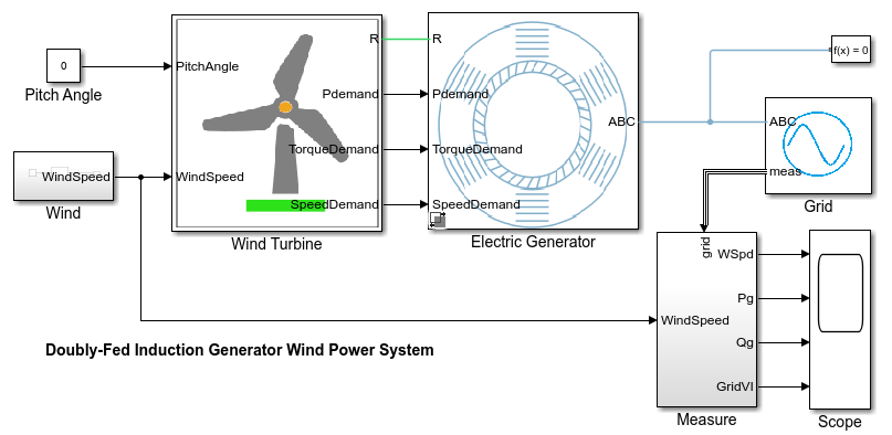
Open the DFIGWindPowerSystem model. The model consists of a wind turbine, a doubly-fed induction generator, a grid-side converter, a rotor-side converter, and the connection to the grid.
modelName = "DFIGWindPowerSystem";
open_system(modelName);
Select Low-Fidelity Electric Generator Model
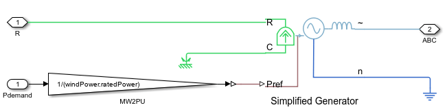
To perform planning and pitch control studies, use the low-fidelity electrical model. The low-fidelity model uses the Simplified Generator block to model the induction generator of the wind system.
To select the low-fidelity model, at the MATLAB® Command Window, run:
simulation.sampleTime = setModelFidelity(Generator="SimplifiedGenerator",SampleTime=simulation.sampleTimeAvgConverter);
.
Select DFIG Wind Power System Model
To simulate the controller, converters, wind turbine, and induction generator, use the detailed DFIG wind power system. This model helps you to design the controller and the power converters and study the dynamic response of the system. The detailed DFIG wind power system models the grid-side converter, rotor-side converter, and DFIG machine.
To select the DFIG generator model with grid-side and rotor-side converter, at the MATLAB Command Window, run:
simulation.sampleTime = setModelFidelity(Generator="DFIGenerator",SampleTime=simulation.sampleTimeAvgConverter);
Open DFIG Subsystem
To open the DFIG subsystem, after you selected the DFIG generator model with grid-side and rotor-side converter, at the MATLAB Command Window, run:
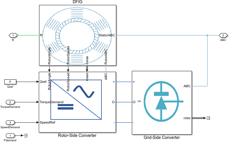
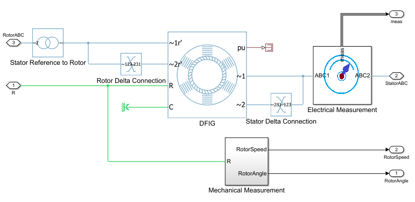
open_system("DFIGWindPowerSystem/Electric Generator/DFIG Generator/DFIG")
To convert the actual rotor voltage and current into stator-referenced rotor voltage and current, the subsystem adds a transformer between the rotor-side converter and the DFIG rotor circuit terminals.
Open Grid-Side Converter Subsystem
To open the Grid-Side Converter subsystem, after you selected the DFIG generator model with grid-side and rotor-side converter, at the MATLAB Command Window, run:
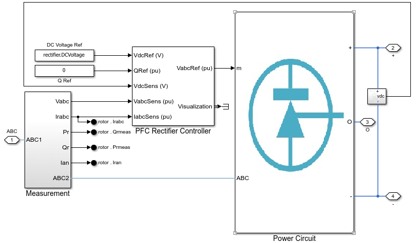
open_system("DFIGWindPowerSystem/Electric Generator/DFIG Generator/Grid-Side Converter")
The grid-side converter converts the three-phase AC grid voltage into a stable DC voltage for the rotor-side converter. The example provides three fidelity levels for the grid‑side converter power circuit: average, two‑level switching, and three‑level switching. To set the fidelity level, specify "GridAverage", "GridTwoLevel", or "GridThreeLevel" for the GridSideConverter name-value argument of the setModelFidelity function, respectively.
For example, to select the average fidelity level, at the MATLAB Command Window, run:
simulation.sampleTime = setModelFidelity(Generator="DFIGenerator",GridSideConverter="GridAverage", ...
    SampleTime=simulation.sampleTimeAvgConverter);
Open Rotor-Side Converter Subsystem
To open the Rotor-Side Converter subsystem, after you selected the DFIG generator model with grid-side and rotor-side converter, at the MATLAB Command Window, run:
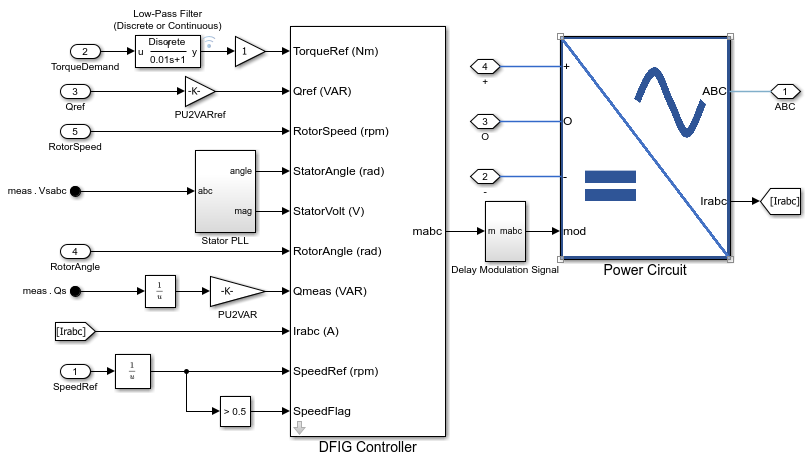
open_system("DFIGWindPowerSystem/Electric Generator/DFIG Generator/Rotor-Side Converter")
The rotor-side converter controls the DFIG to achieve the required speed, active power, and reactive power. The rotor-side converter is rated at one-third of the rating of the DFIG wind power system. The example provides three fidelity levels for the rotor‑side converter power circuit: average, two‑level switching, and three‑level switching. To set the fidelity level, specify "RotorAverage", "RotorTwoLevel", or "RotorThreeLevel" for the RotorSideConverter name-value argument of the setModelFidelity function, respectively.
To select the average fidelity level, at the MATLAB Command Window, run:
simulation.sampleTime = setModelFidelity(Generator="DFIGenerator",RotorSideConverter="RotorAverage", ...
    SampleTime=simulation.sampleTimeAvgConverter);
Open DFIG Controller Subsystem
To open the DFIG Controller subsystem, after you selected the DFIG generator model with grid-side and rotor-side converter, at the MATLAB Command Window, run:
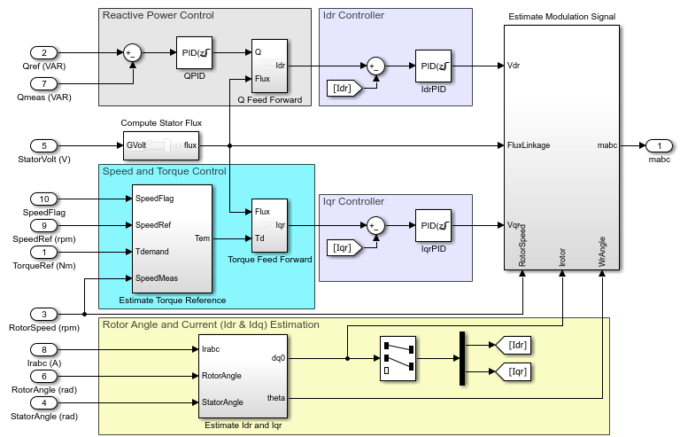
open_system("DFIGWindPowerSystem/Electric Generator/DFIG Generator/Rotor-Side Converter/DFIG Controller")
Use the DFIG controller to control the DFIG machine to achieve the required power and operate the wind power system in both constant speed and maximum power point tracking (MPPT) mode. The DFIG control models three reference frames: the stationary stator reference frame , the rotating stator synchronous reference frame , and the rotor reference frame rotating at generator rotor speed. In this example, the stator flux is aligned with the d-axis of the stator synchronous rotating reference frame.
The DFIG controller controls the torque, speed, active power, and reactive power.
Plot MPPT of Wind Turbine
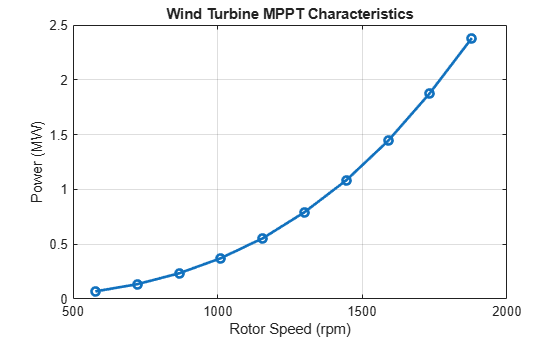
To choose the operating speed range of the DFIG machine and the rating of the rotor-side power converter, plot the maximum power at different wind speeds for the wind turbine and the gear box. Use the estimateWindTurbineMPPTArray function to plot the maximum power and torque against rotor speed. This will help you to design the MPPT algorithm, select the gear ratio, and analyze the maximum output power supplied by the wind turbine with the given gear ratio at the zero pitch angle.
DFIGWindPowerSystemInputParameters;
turbineSpeedRange = simscape.Value([0.4 2.5]*dfig.syncSpeed,"rpm");
windSpeedArray = simscape.Value(4:1:13,"m/s");
windMPPT = estimateWindTurbineMPPTArray(TurbineSpeedRange=turbineSpeedRange,WindSpeedArray=windSpeedArray);
Simulate DFIG Wind Power System
Select the required model fidelity for the DFIG generator, rotor-side converter, and grid-side converter, simulate the model, and visualize the results. For example, to select the full DFIG model with average rotor-side and grid-side converter, specify the Generator, RotorSideConverter, GridSideConverter name-value argument as "DFIGenerator", "RotorAverage", and "GridAverage", respectively.
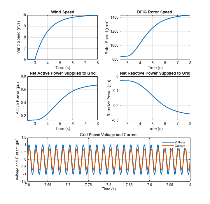
Run the simulation and plot the results for wind speed, DFIG rotor speed, net active power supplied to the grid, net reactive power supplied to the grid, and grid phase voltage and current.
DFIGWindPowerSystemInputParameters;
simulation.sampleTime = setModelFidelity(Generator="SimplifiedGenerator", ...
    SampleTime=simulation.sampleTimeAvgConverter);
SimlogData = sim(modelName); % Simulate the model
plotDFIGWindPowerSystem(SimlogData); % Plot the simulation result