Getting Started with STM32H7RSxx Based Microcontroller Series
R2026bThis example shows how to configure a Simulink® model for the STM32H7RSxx family of microcontrollers and deploy an application to the STMicroelectronics® NUCLEO-H7S3L8 board.
The STM32H7Rx/Sx family is based on the ARM® Cortex®-M7 processor and runs at frequencies up to 600 MHz. These devices include 64 KB of internal BootFlash and 620 KB of SRAM. The internal BootFlash is intended for boot code and small applications, while larger applications can be stored in external memory connected through the XSPI interface.
In this example, you configure a Simulink model to blink the green (LD1), yellow (LD2), and red (LD3) LEDs on the NUCLEO-H7S3L8 board.
Choose an Execution Method
STM32H7RSxx devices support two execution methods. Select the execution method that best fits your application requirements.
Internal Flash
Use the Internal Flash execution method when the generated application fits within the available 64 KB BootFlash memory.
The application is programmed into internal flash memory and executes directly from the device. When using this execution method, configure all peripherals in the Boot runtime context in STM32CubeMX.
Load and Run (LRUN) from External Memory
Use the Load and Run (LRUN) execution method when the application exceeds the available internal BootFlash memory.
Use this mode to load code into external flash memory connected via the XSPI interface. During execution, code is copied from external flash into internal SRAM for fast execution. All peripherals must be configured in Application context.
Prerequisites
If you are new to Simulink, we recommend completing the Simulink Onramp interactive tutorial to get started.
Watch this STM32CubeMX GPIO configuration video for an introduction to STM32CubeMX.
Both the workflows in this example use STM32CubeMX to configure board peripherals and generate initialization code for the STM32H7RSxx device. You can either create a new STM32CubeMX project or use an existing project file (.ioc). Simulink allows you to open and modify the STM32CubeMX project directly from the model configuration settings. For more information, see STM32CubeMX overview.
Required Hardware
To run this example, you need the following hardware:
USB Type-C cable
NUCLEO-H7S3L8 board
GPIO Assignments
The example uses the following pins:
PC13 - GPIO Input (User Button) - Enable internal pull-up
PD10 - GPIO Output (Green LED)
PD13 - GPIO Output (Yellow LED)
PB7 - GPIO Output (Red LED)
Run Hardware Board Setup
Run the following command in the MATLAB Command Window to launch the Hardware Setup wizard. Follow the guided steps to register the STMicroelectronics software tools needed for code generation and deployment.
stm32setup
Select STM32H7RSxx Based MCUs to add support for the STM32H7RSxx MCU family.
Workflow-1: Deploy to Internal Flash
Use this workflow to build and run an application directly from the device BootFlash memory. In this workflow, you use the preconfigured project file H7RSGettingStartedIOC.ioc and then complete the remaining hardware and model configuration steps.
Run this command to open the model:
open_system("stm32h7rs_gettingstarted.slx")Configure the Simulink Model
1. Open Configuration Parameters by pressing Ctrl+E.
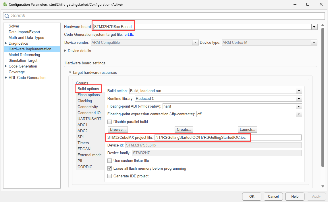
2. Navigate to Hardware Implementation > Hardware board, and select STM32H7RSxx Based.
3. Under Build options tab, select the provided STM32CubeMX project:H7RSGettingStartedIOC.ioc
4. Under Flash options, set Execution method to Internal Flash.
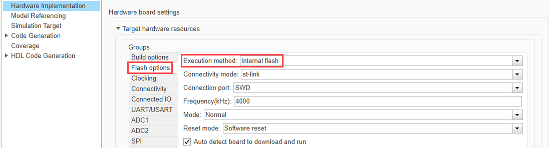
With this setting, when you build and deploy the model, Simulink downloads the executable directly into internal flash and starts execution without programming external flash memory.
Configure the STM32CubeMX Project
Launch STM32CubeMX from Simulink and configure the required peripherals.
Configure GPIO Pins
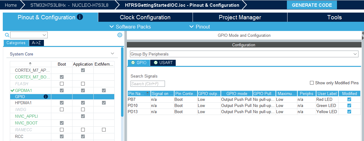
Configure the following pins in the Boot runtime context.
Pin | Mode | Label |
PB7 | GPIO_Output | Red LED |
PD10 | GPIO_Output | Green LED |
PD13 | GPIO_Output | Yellow LED |
For each GPIO output pin, configure the following parameters:
Pin Context Assignment: Boot
GPIO output level: Low
GPIO mode: Output Push Pull
GPIO Pull-up/Pull-down: No pull-up and no pull-down
Maximum output speed: Low
Configure the System Time Base
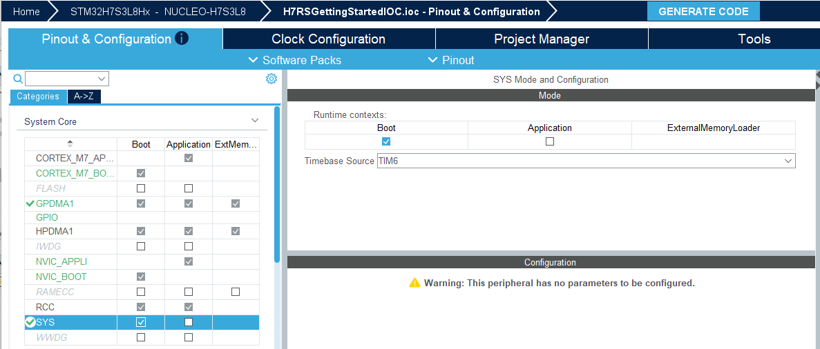
Open System Core > SYS_S.
Enable Boot as the runtime context.
Set Timebase Source to TIM6.
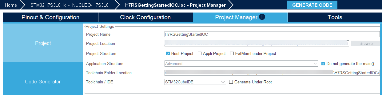
Configure Project Settings
In Project Manager, configure:
Project Name: H7RSGettingStartedIOC
Project Structure: Select Boot Project
Application Structure: Select Do not generate the main()
Toolchain: STM32CubeIDE
Build and Deploy the LED Blink Application
Open the Simulink model:
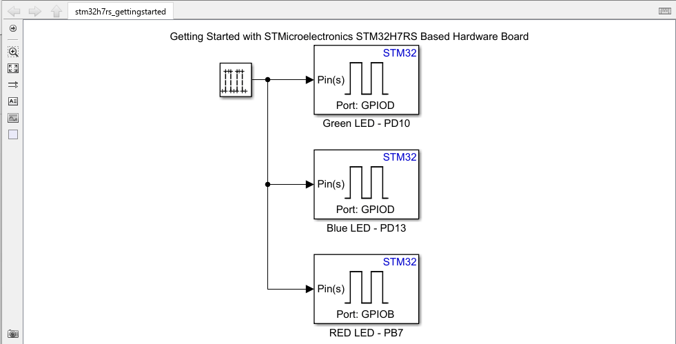
open_system("stm32h7rs_gettingstarted.slx");The model uses Digital Port Write blocks to control the three LEDs on the NUCLEO-H7S3L8 board.
Configure the Digital Port Write Block
Open the block mask of each Digital Port Write block and configure the parameters:
Green LED: Port GPIOD, Pin 10
Yellow LED: Port GPIOD, Pin 13
Red LED: Port GPIOB, Pin 7
Additionally, select the Access port pins as array block parameter.
Build and Deploy
Press CTRL+B or click the Build, Deploy & Start button on the Hardware tab to generate code and deploy to the board.
Observe the green LED blinking on the NUCLEO-H7S3L8 board.
To view build diagnostics and generated code, see the Diagnostic Viewer.
Workflow 2: Deploy by Using Load and Run (LRUN)
The STM32H7Rx/Sx family uses a BootFlash architecture that combines a small internal flash memory with external memory support for larger applications. The 64 KB internal BootFlash is used for the initial boot process, while the main application can reside in external flash memory. When the application exceeds the available BootFlash capacity, use the Load and Run (LRUN) execution method. In LRUN mode, the boot code loads the application image from external flash into internal SRAM and then transfers execution to the application.
An LRUN project in STM32CubeMX is organized into three sub-projects that work together during programming and execution.
Boot Project
The Boot project executes from internal BootFlash. It performs device initialization, configures the external memory interface, and launches the application by using the External Memory Manager middleware.
Application Project
The Appli (Application) project contains the user application stored in external flash memory. During startup, the Boot project copies the application into internal SRAM before execution begins. Configure application-level peripherals in the Application runtime context.
External Memory Loader Project
The ExtMemLoader project generates an external loader (.stldr) file that STM32CubeProgrammer or supported IDEs use to program the external flash device.
The External Memory Manager (EXTMEM_MANAGER) middleware provides a common framework for accessing external memory devices and includes the boot services required for loading and starting the application in LRUN mode.
The External Memory Loader middleware generates target-specific loader entry points that are compatible with development environments such as STM32CubeIDE, IAR Embedded Workbench®, and Keil® MDK.
For more information, see Getting started with External Memory Manager and External Memory Loader.
Configure the Simulink Model for LRUN
Run this command to open the multi-rate Simulink model:
open_system('stm32h7rs_gettingstarted_multirate');In this workflow, you use the preconfigured project file H7RSGettingStartedMultiRateIOC.ioc and then complete the remaining hardware and model configuration steps.
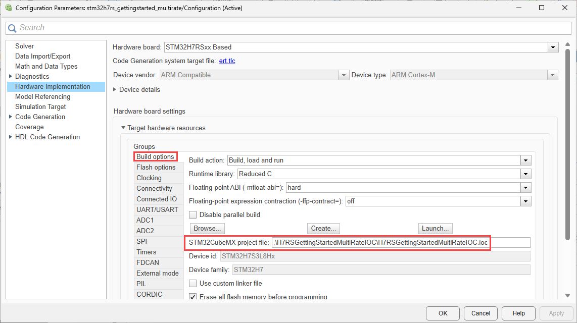
1. Open Configuration Parameters by pressing Ctrl+E.
2. Navigate to Hardware Implementation > Hardware board, and select STM32H7RSxx Based.
3. Under Flash options, set Execution method to Load and Run (LRUN) from external memory.
4. For the NUCLEO-H7S3L8 board, select the external loader: MX25UW25645G_NUCLEO-H7S3L8.stldr.
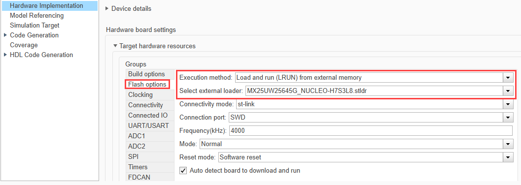
Note: STM32CubeProgrammer includes external loaders for many ST evaluation boards and supported flash memory devices, which you can select directly from the loader list. For custom boards, ensure that the selected .stldr file supports the external flash memory device installed on the board. If your flash device is not supported by the loaders included with STM32CubeProgrammer, create or obtain a compatible .stldr file and specify it using the Custom loader option in the Flash options settings.

5. Under Build options tab, select the provided STM32CubeMX project: H7RSGettingStartedMultiRateIOC.ioc
Configure the STM32CubeMX Project
The STM32CubeMX project for LRUN mode requires configuration of the external memory interface, the External Memory Manager middleware, the project structure, and the GPIO peripherals.
Configure the XSPI peripheral before configuring EXTMEM_MANAGER. The External Memory Manager uses the XSPI peripheral to communicate with external flash memory. If you configure EXTMEM_MANAGER before XSPI, the required XSPI peripheral might not be available in the middleware configuration.
Configure XSPI2 in Boot Context
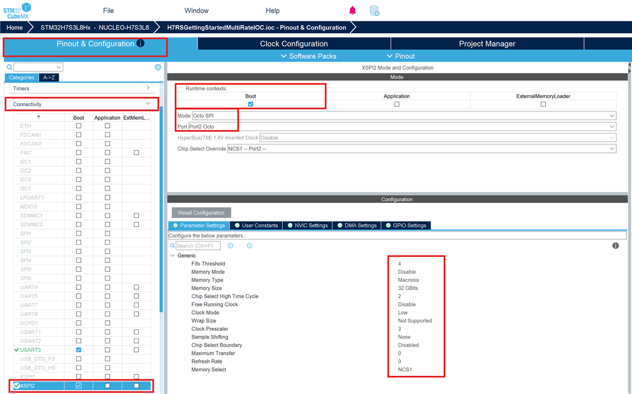
The XSPI peripheral interfaces with the external NOR flash memory. Configure the XSPI instance that matches your board hardware in the Boot runtime context because the boot code uses this peripheral to access external memory.
The XSPI module interfaces with the external NOR flash memory. Configure the appropriate XSPI instance for your board in Boot context, since it is needed during the boot phase to access external memory.
In STM32CubeMX, go to Pinout & Configuration > Connectivity and select the XSPI instance for your board (XSPI2 for NUCLEO-H7S3L8). Set Runtime contexts: Boot.
Configure the mode, port, and parameter settings as per your hardware.
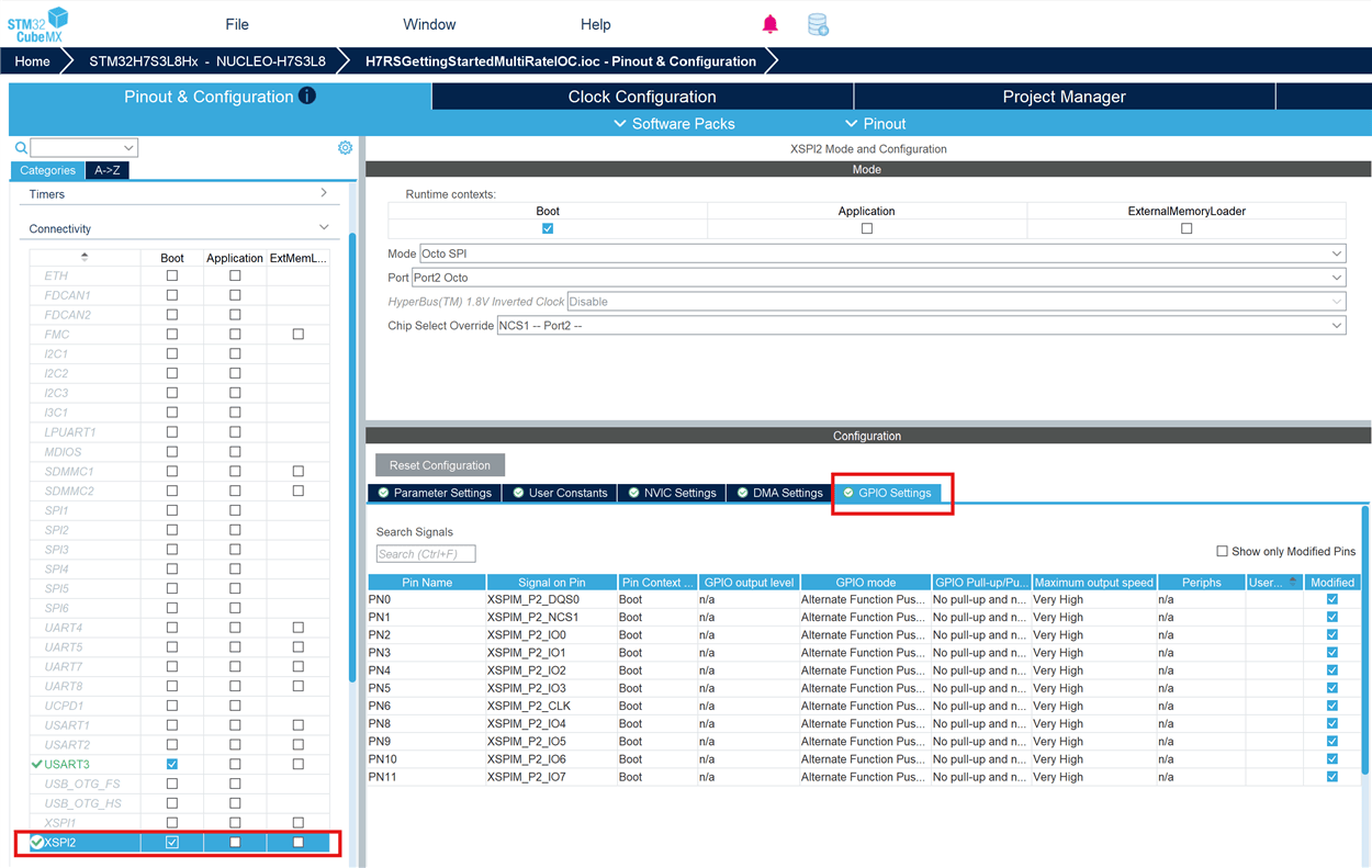
Assign the correct GPIO pins to the XSPI module as per your hardware connections. This image shows the pin assignments for the NUCLEO-H7S3L8 board.
Configure External Memory Manager Middleware
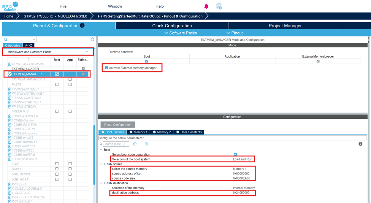
Go to Pinout & Configuration > Middleware and Software Packs > EXTMEM_MANAGER:
Activate the EXTMEM_MANAGER middleware in Boot context.
In Boot usecase tab:
Select Select boot code generation
Selection of the boot system: Load and Run
Configure the LRUN source address offset, code size, and destination address as per your application. This image shows the configuration for the NUCLEO-H7S3L8 board.
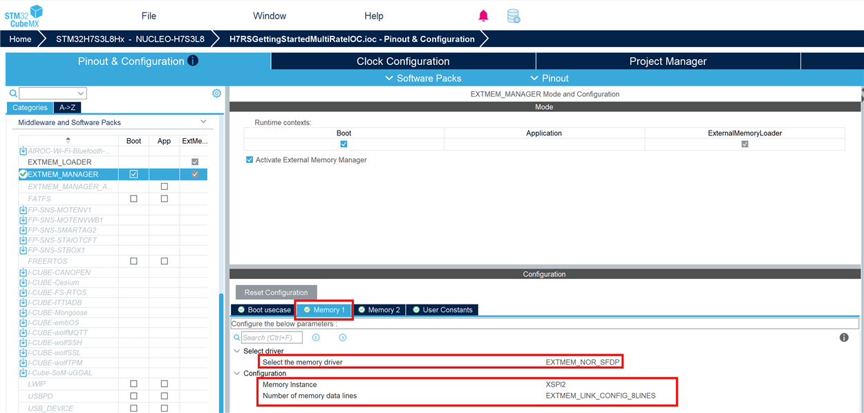
In Memory 1 tab, configure:
Memory Instance: XSPI2
Number of memory data lines: EXTMEM_LINK_CONFIG_8LINES
Configure Project Manager
Go to the Project Manager tab in STM32CubeMX:
Project Structure: Select Boot Project and Appli Project
Application Structure: Select Do not generate the main()

Under Project Manager > Advanced Settings > Driver Selector, configure the following driver layers:
CORTEX_M7, RCC, GPDMA, GPIO, USART: LL
XSPI, EXTMEM_MANAGER: HAL

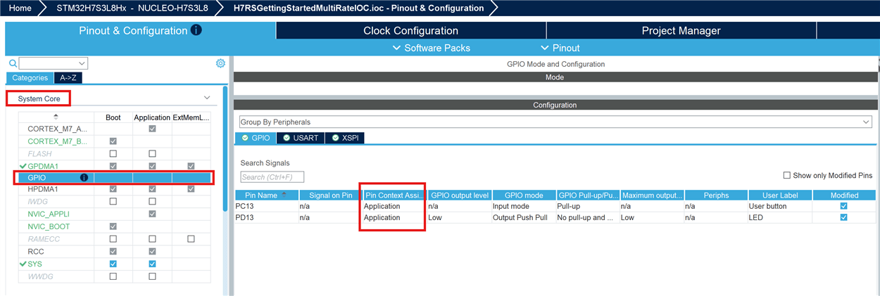
Configure GPIO Pins (Application Context)
Because the application code executes in Application context in LRUN mode, the GPIO pins must be configured in Application context.
PC13 - GPIO Input (Application context)
PD13 - GPIO Output (Application context)
Build and Deploy the Multi-rate LED Blink Application
Open the Simulink model:
open_system("stm32h7rs_gettingstarted_multirate.slx");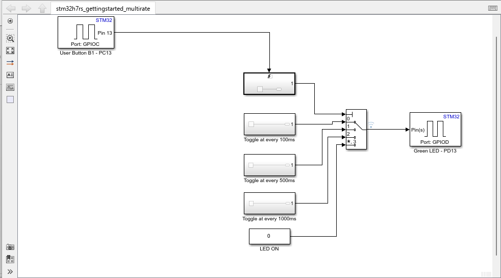
Configure the Digital Port Read and Digital Port Write blocks in the model for the desired GPIO pins.
Digital Port Read (User Button): Port GPIOC, Pin 13
Digital Port Write (Green LED): Port GPIOD, Pin 13
The model toggles the LED at multiple rates (100 ms, 500 ms, 1000 ms) based on the user button input.
After configuring the Simulink model and STM32CubeMX project:
Press CTRL+B or click the Build, Deploy & Start button on the Hardware tab to generate code and deploy to the board.
Observe the LEDs blinking at varying rates on the NUCLEO-H7S3L8 board.
To view build diagnostics and generated code, see the Diagnostic Viewer.
Review Block Library for STM32H7RSxx Series
You can explore all the blocks available for the STM32H7RSxx series by opening the corresponding Simulink Library Browser:
open_system('stm32h7rsxxblockslib');The library contains blocks for GPIO, ADC, UART, SPI, Timers, and other peripherals supported on your STM32H7RSxx board.
Other Things to Try
Configure a Hardware Interrupt block to generate interrupt service routines that execute in response to external events.
Use the Digital Port Read block to read the user button (PC13) and control LED behavior based on button press.
Explore the ADC and UART blocks available in
stm32h7rsxxblockslib.

