MCPWM
R2026bGenerate PWM signals using the MCPWM peripheral on F28E12x C2000 processors
Since R2026b
MCPWM block
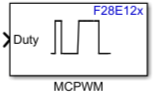
To add a block to a model, double-click the canvas and start typing the block name. Then, select the block from the list.
Libraries:
C2000 Microcontroller Blockset /
F28E12x
Description
The MCPWM block controls the Multi-Channel Pulse Width Modulation (MCPWM) peripheral on Texas Instruments® F28E12x C2000™ processors to generate single or complementary PWM output signals for motor control, power conversion, and other switching applications.
The block accepts duty cycle values at each time step and writes them to the appropriate compare registers. Specify the duty cycle as a percentage or as raw timer counts. When you select both A and B outputs for a channel, the block accepts a two-element vector to independently control each output.
Ports
Input
Parameters
Algorithms
At each time step, the block calls hardware-specific C functions to update the MCPWM peripheral registers:
| C Function | Register Updated | Purpose |
|---|---|---|
updateCMP
|
CMPxS
| Write compare values to the selected PWM channel |
updateTBPRD
|
TBPRDS
| Update time base period in raw counts |
updateTBPRDFromSeconds
|
TBPRDS
| Convert seconds to counts and update time base period |
updatePHSDIR
|
TBCTL.PHSDIR
| Set phase counting direction after sync |
updateSWSYNC
|
TBCTL.SWSYNC
| Trigger software synchronization pulse |
updateSFRC
|
AQSFRC
| Apply continuous software force action to outputs |
When the timer period unit is set to seconds, the block converts the period value using the formula:
For up-count mode: TBPRD = (period_seconds * CPU_CLK) /
prescaler_divider
For up-down count mode: TBPRD = (period_seconds * CPU_CLK) / (2 *
prescaler_divider)
The CPU_CLK value comes from the system clock configuration, and
prescaler_divider is set in Target hardware
resources > MCPWM in the model
Configuration Parameters.

