Using Comparator Subsystem (CMPSS) for Voltage Compare
R2026bThis example shows how to use the Comparator Subsystem (CMPSS) to compare the analog voltage signals for Texas Instruments™ C2000™ processors and monitor the status output. Using this example, you can:
Configure the CMPSS module to generate the digital output when there is a voltage difference on the input pins.
Configure Digital Filter to generate filtered output for CMPSS.
Configure positive and negative pins of the CMPSSxy module (x = module number, y = H/L) in the Configuration Parameters window.
Introduction
The CMPSS consists of two modules, Comparator High (COMPH) and Comparator Low (COMPL). Each module generates a high digital output when the voltage on the first input pin (positive input) is greater than the voltage on the second input pin (negative input). Vice versa it generates low digital output when the voltage on the first input pin (positive input) is less than the voltage on the second input pin (negative input).
The second input pin can either be the external pin or the internal CMPSS DAC module.
Required Hardware
This example contains preconfigured example models for the following hardware:
TI Delfino F28379D LaunchPad
TI Piccolo F280049C LaunchPad
TI F29H85x LaunchPad
TI F28P65x LaunchPad
Available Models
f2837x_cmpss.slx
f28004x_cmpss.slx
f28p65x_cmpss.slx
f28p65x_cmpss_external.slx
f29h85x_cmpss.slx
Hardware Connections for TI Delfino F28379D LaunchPad
CMPSS1
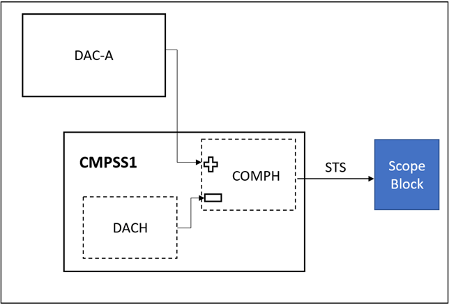
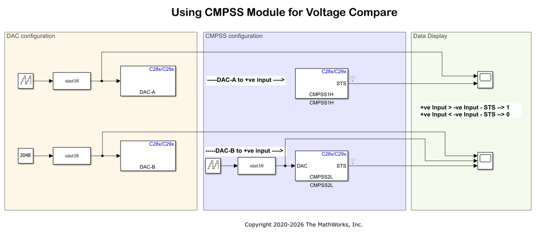
1. DAC- A is connected to the positive input of the CMPSS1H comparator (COMPH of CMPSS1).
2. Configure the negative input to the internal DAC of CMPSS1(DACH).
3. COMPH actively compares the input voltages on its input pins and provides the STS output.
CMPSS2
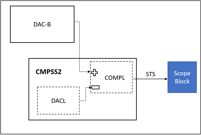
1. DAC- B is connected to the positive input of the CMPSS2L comparator (COMPL of CMPSS2).
2. Configure the negative input to the internal DAC of CMPSS2(DACL).
3. This COMPL actively compares the input voltages on its input pins and provides the STS output.
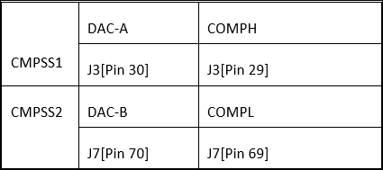
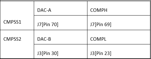
Connect the launchpad header pins for TI Delfino F28379D LaunchPad as listed below.
Hardware Connections for TI F28P65x LaunchPad
Two preconfigured models are available for the TI F28P65x LaunchPad:
f28p65x_cmpss.slx (Internal DAC as negative input)
DAC A is connected to J3 Pin 28 (B7) - positive input of the CMPSS module.
DAC C is connected to J7 Pin 67 (A10) - positive input of another CMPSS module.
Negative inputs are provided by the internal DAC.
f28p65x_cmpss_external.slx (External DAC as negative input)
This model demonstrates using both external DAC pins as positive and negative inputs to CMPSS 5, eliminating the use of the internal DAC for the negative reference.
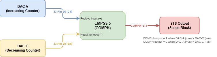
DAC A is connected to J3 Pin 26 (C4) - positive input of CMPSS 5.
DAC C is connected to J3 Pin 25 (B4) - negative input of CMPSS 5.
DAC A uses an increasing counter (ramp up) as the positive input signal.
DAC C uses a decreasing counter (ramp down) as the negative input signal.
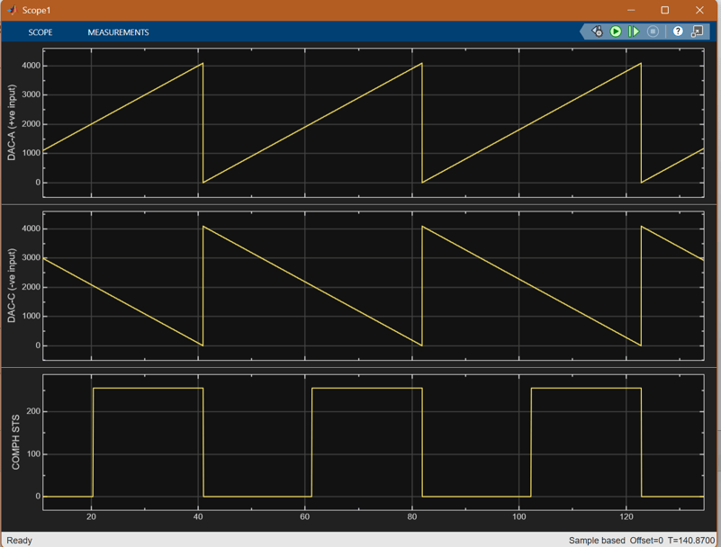
COMPH outputs 1 when DAC-A voltage exceeds DAC-C voltage, and 0 otherwise.
Model
Using CMPSS Module for Voltage Compare Model
Open the f2837x_cmpss.slx model.
Configure the Model
1. Open the Using CMPSS Module for Voltage Compare Model model. This model is configured for TI Delfino F28379D LaunchPad hardware.
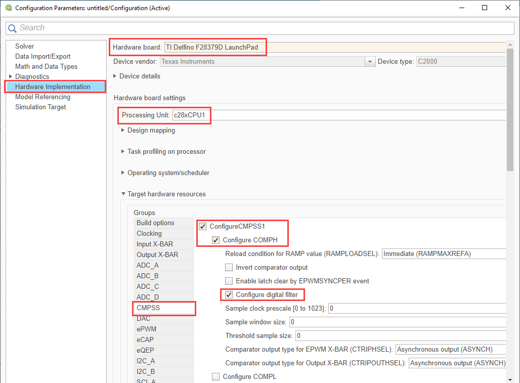
2. To run the model on other TI C2000 processors, press Ctrl+E to open the Configuration Parameters dialog box and select the required hardware board by navigating to Hardware Implementation > Hardware board.
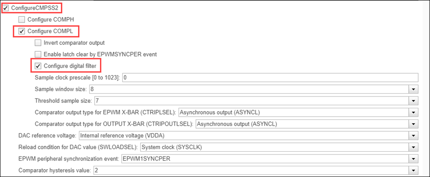
3. The following are the comparator configurations performed in the model. Ensure that the specified parameter values are the same if you want to run this example for other hardware board.
Configure CMPSS1 with COMPH
Configure CMPSS2 with COMPL
CMPSS Block Configurations
Following are the CMPSS block configurations done for this model. Double-click on the blocks to open block parameter configurations. Ensure the specified parameter values are the same if you want to run this example for other hardware board
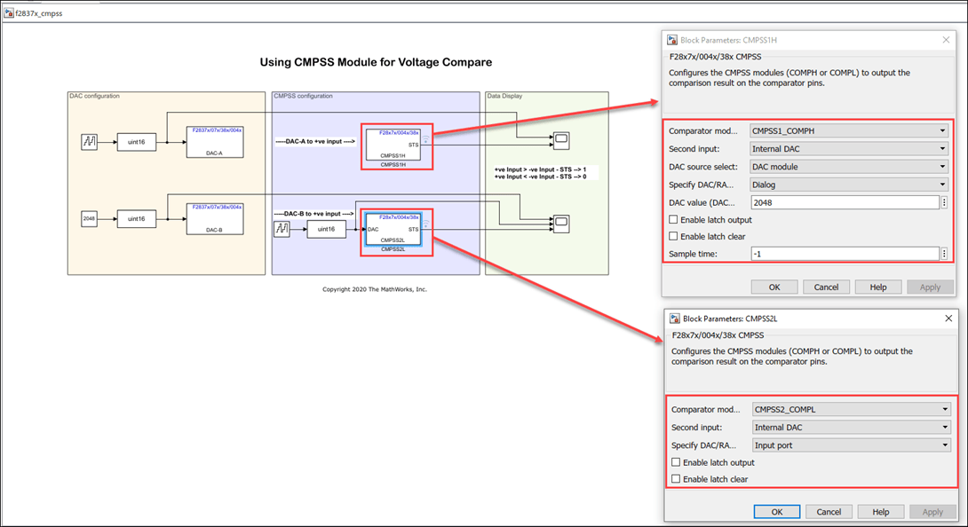
For newer processors starting with F28004x, you can select the input connections to the CMPSS modules through a programmable input mux. The positive and negative pin connections for COMPH and COMPL can be configured directly in the Configuration Parameters dialog under the CMPSS settings. Use the COMPHP pin and COMPHN pin dropdowns to select the appropriate analog input pin for each comparator module.

For more information, see CMPSS.
Run the Model
1. Open Hardware tab and click Monitor & Tune.
2. Use the diagnostic viewer to follow the build progress and wait until the code loads and runs on the target hardware.
3. Observe the logged data on the Scope block.
Analysis of DAC and CMPSS output signals
This section explains how to interpret the DAC-A and COMPH for CMPSS1.
DAC-A voltage value ranges from 0-4095 which gives a Ramp voltage(0-3.3v) on the DAC-A pin. This voltage is fed to positive input of the CMPSS1 COMPH comparator.
The internal DAC (DACH) of the CMPSS1 is configured to output a constant voltage of 2048(1.65v).
The model is configured to run at a step time of 10ms. It will take 10ms * 4095 = 40.950 seconds for the DAC-A output to reach from 0 to 3.3V.
The COMPH outputs 0 for the first half as the voltage on the positive input is less than the constant voltage (1.65v) on negative input. It then outputs 1 for second half as the voltage on the positive input is now more than the constant voltage (1.65v) on negative input.
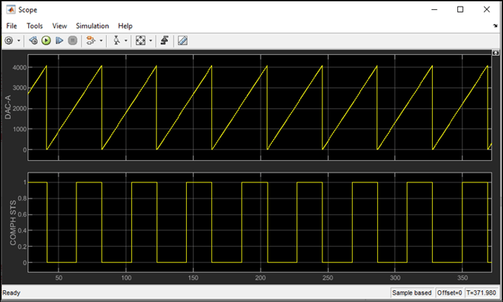
Similar interpretation can be done for DAC-B and CMPSS2 from the Scope plot.
Analysis of F28P65x External Model Signals
In the f28p65x_cmpss_external.slx model, both positive and negative inputs of CMPSS 5 are driven by external DAC pins.
DAC-A provides an increasing ramp (0-4095) as the positive input.
DAC-C provides a decreasing ramp (4095-0) as the negative input.
COMPH outputs 1 when DAC-A exceeds DAC-C and 0 otherwise.
Other things to try
Run the example on the f28004x_cmpss.slx
TI Piccolo F280049C LaunchPadhardware board.Connect the launchpad header pins for TI Piccolo F280049C LaunchPad as listed below.
Run the example on the f28p65x_cmpss.slx
TI F28P65x LaunchPadhardware board with internal DAC as negative input.Run the f28p65x_cmpss_external.slx model to observe CMPSS behavior with external DAC signals on both positive and negative inputs.

