Digital DC/DC Buck Converter Using Peak Current Mode Control
This example shows how to use the Comparator Subsystem (CMPSS) to regulate buck converter output voltage (BOOSTXL-BUCKCONV) using Peak Current Mode Control (PCMC) for Texas Instruments™ C2000™ Microcontroller Blockset. Using this example, you can:
Configure the CMPSS to monitor the inductor current sense feedback (ILFB) signal.
Configure the enhanced Pulse Width Modulator (ePWM) to trip on an overcurrent condition.
Generate code for the controller and load it on the hardware board.
Monitor signals and tune parameters on the host computer.
Introduction
This example uses a CMPSS, an ePWM, and ADC (Analog Digital Converter) subsystem to perform the synchronous buck operation in PCMC.
Each PWM cycle starts by driving the ePWM high (PWM-HI) until the peak current threshold is reached after which the PWM-HI signal is driven low for the rest of the PWM cycle.
The ePWM1 module triggers ADC conversions to sense the plant feedback signals at a frequency of 200kHz.
The ADC ISR calculates changes to the peak current limit.
An on-chip analog CMPSS is configured to continuously monitor the current sense feedback (ILFB) signal against set peak current limit.
The Control Law Accelerator (CLA) executes the PCMC control algorithm.

Required Hardware
9V external power supply
Micro-USB cable
Available Models
f280049C_DCDC_Buck_PCMC -
Digital DC/DC Buck Converter Peak Current Mode Control (PCMC)can be used to generate code and load it on the F80049C LaunchPad.c2000_host_read_PCMC -
Host PCMC Modelcan be run on the host computer to log signals and tune parameters.
Hardware Connections
Connect the Digital Power Buck Converter BoosterPack (BOOSTXL-BUCKCONV) to the Texas Instruments Piccolo F280049C LaunchPad as detailed in the following table. For more information, refer C2000 Digital Power Booster Pack
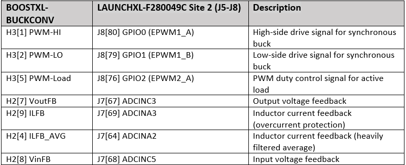
Note: Ensure that a jumper is present between pins +3v3 TO J5 on the JP8 on the launchpad.
Model
Digital DC/DC Buck Converter Peak Current Mode Control (PCMC) Model
To open the f280049C_DCDC_Buck_PCMC model.
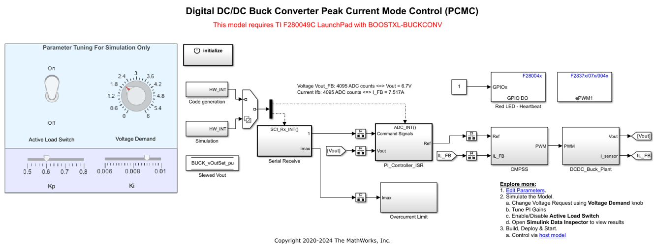
C2000_host_read_PCMC Model
To open the c2000_host_read_PCMC model.
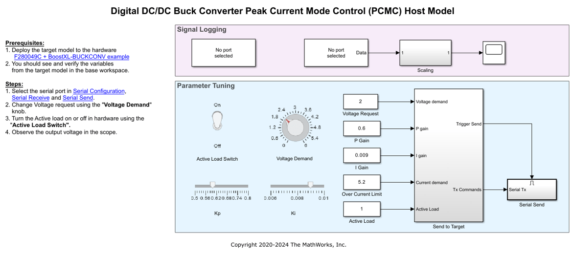
This example demonstrates the working of PCMC for a fixed input voltage of 9 V DC and an output voltage setpoint of 2 V DC. Hence a fixed slope compensation value is applicable for the above mentioned voltages is computed. For more information, refer to TI manual 'Digital Peak Current Mode Control With Slope Compensation'.
For simulation, the RAMP Generator has been implemented and SR flip flop block is used to generate PWMs to implement the comparator logic in Simulink®.
Configure and Run Digital DC/DC Buck Converter Peak Current Mode Control (PCMC) Model
1. Open the f280049C_DCDC_Buck_PCMC model. This model is configured for TI Piccolo F280049C LaunchPad hardware.
2. To run the model on other TI C2000 processors, first press Ctrl+E to open the Configuration Parameters dialog box. Then, select the required hardware board by navigating to Hardware Implementation > Hardware board.
Note: Ensure that the Digital Power Buck Converter BoosterPack is connected to the selected hardware board with correct pin mappings.
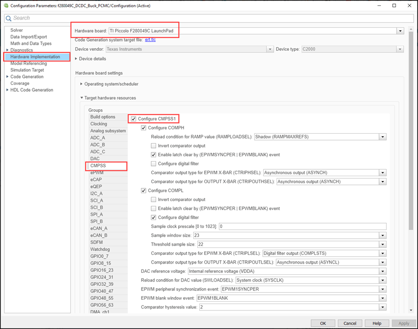
3. The following screenshots show the CMPSS configurations performed in the model. You can use the same parameter values if you want to run this example for other hardware boards.
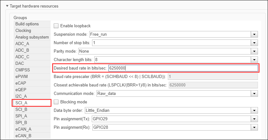
4. Ensure that the baud rate is set to 6250000 bits/sec.
Peripheral Block Configurations
Set the peripheral block configurations for this model. Double-click on the blocks to open block parameter configurations. You can use the same parameter values if you want to run this example for other hardware boards.
ePWM block
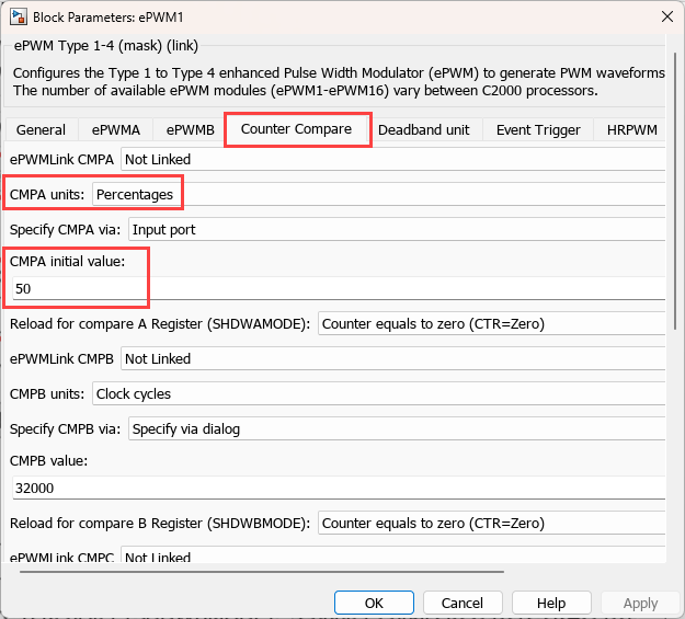
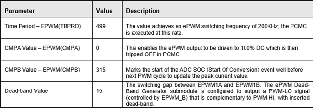
Configure the ePWM action qualifier to generate waveforms based on digital compare events. Configure the trip signal generated by the CMPSS module to trip ePWMA to low.

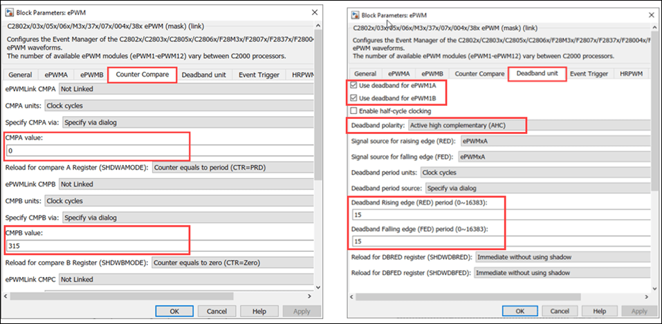
The CMPSS output is passed through a filter and also blanking window is used so that ePWM does not respond to any noise or spurious signals as shown in the following figure.

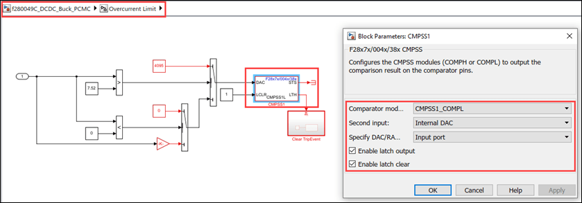
CMPSS Block in Overcurrent Limit
The overcurrent logic trips the output on an overcurrent condition. Although overcurrent protection is inherent in the peak current loop, the application implements a redundant protection path using spare comparator resources on the MCU. This trip is configured for one shot trip in the ePWM. Clear the trip flags to re-enable the outputs.
CMPSS Block in CLA Task
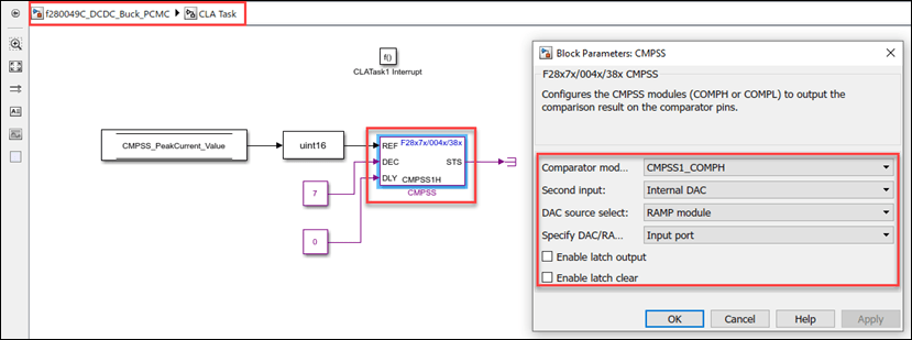
The PCMC control algorithm is executed by CLA module, which generates an interrupt to the CPU when the algorithm is executed. The CMPSS with computed peak current threshold is updated within the CLA interrupt routine. For information on the CLA configuration, refer to Using the Control Law Accelerator (CLA).
The comparator monitors the inductor feedback current against the peak current threshold. It generates a trip signal for the ePWM when the current limit is met.
The peak current threshold for the comparator is provided by a reference DAC. Use the ramp generator to control the reference DAC values, which are synchronized to an ePWM
The RAMP decrement value, which defines the slope of the RAMP signal, is fixed to 7. This fixed slope might not cover the full dynamic range of the operation of the plant using PCMC.
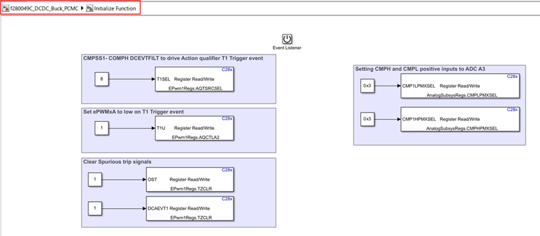
In order to switch ePWM based on comparator output the following configurations are made in the Initialize subsystem in the model.
1. CMPSSH and CMPSSL positive inputs are connected to the ADC output using Analog subsystem registers.
2. The CMPSSH output is used to create digital compare event (DCEVT) whose filtered version acts as a source for the ePWM T1 event. This is done using the AQTSRCSEL register.
3. The ePWM is set to low when ePWM T1 event occurs. This configuration is done using the AQCTLA2 register.
ADC Block in PI Controller ISR
The ePWM triggers the ADC start of conversion (SOC) event to sample the output voltage. The ADC end of conversation (EOC) interrupt executes the digital control algorithm that computes the actuation value depending on the error in the system.

Simulate Peak current mode Control for DC/DC Buck Converter Plant Model
Run the Model
1. Open the f280049C_DCDC_Buck_PCMC model.
2. Click Run on the Simulation tab to simulate the model.
3. Click Data Inspector on the Simulation tab to view and analyze the simulation results. You can tune the input parameters using the dashboard controls.
Generate Code for Controller and Load on Hardware Board
1. To generate the code for the model f280049C_DCDC_Buck_PCMC , press Ctrl+B or click Build, Deploy & Start.

2. Follow the build process by opening the diagnostic viewer using the link provided at the bottom of the model canvas. After you load the code on the board, a red LED blinks on the hardware board, indicating that the code is running.
Monitor Signals and Tune Parameters on Host Computer
Configure and Run Model on Host Computer
1. On the host computer, browse to Device Manager > Ports (COM & LPT) to find the COM port.
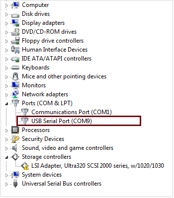
2. Set the COM ports of the following blocks in the c2000_host_read_PCMC model to match the COM port of the host computer:
c2000_host_read_PCMC > Serial Receive
c2000_host_read_PCMC > Serial Send > Serial Send1
3. Click on the Run button to run the model.
Tune Parameters
While the model runs, you can tune parameters using the following dashboard blocks:
Voltage Request - Change the output voltage demand. This parameter is the main request for the control loop. The controller algorithm compares the Voltage Request value with the measured output voltage and adjusts the PWM duty cycle towards achieving the output voltage.
P Gain - Change the proportional gain of the controller algorithm. You can change this parameter to study the robustness of the controller. Large, abrupt changes might lead to instability of the controller; apply changes smoothly.
I Gain - Change the integral gain of the controller algorithm. You can change this parameter to study the robustness of the controller. Large, abrupt changes might lead to instability of the controller; apply changes smoothly.
Over Current Limit - Change the overcurrent setpoint to be less than the current operating in the converter. For example, when the controller is regulating the Vout at 2 V, try to program the overcurrent limit to 1.2 A. This should trip the outputs to the plant as the over current condition occurred.
Active load - Turn the active load present on the hardware on or off. This parameter allows you to add an extra load resistor to study the effect of abrupt changes in the load circuit.
Monitor Signals
While the model runs, you can monitor the following signals on the Scope block:
V_FB Voltage - The measured output voltage of the system is 2 V.

Active load:

Troubleshooting
Ensure the 9 V DC power supply input voltage is stable when active load is enabled. In the test bench setup, the active load works when input voltage is set to 10 V.
If you face connectivity issues with the serial connection between host and target, try to disconnect and reconnect the TI Piccolo F280049C LaunchPad.
When the current in the converter is more than the overcurrent setpoint, the output gets tripped and the P-I controller reaches saturation. To re-enable the output the below sequence can be followed:
Set the overcurrent limit to a higher value such as 5.2 A.
Set the voltage setpoint to 0 volts and then back to 2 V.
Other Things to Try
Calculate the slope compensation for a different voltage setpoint, configure the comparator and run the example.