Deployment, Connected I/O, and Monitor and Tune
Simulink®, combined with the UAV Toolbox Support Package for ArduPilot® Autopilots, enables efficient development, testing, and validation of control algorithms for ArduPilot-based vehicles. Three primary workflows facilitate each stage of algorithm design and verification:
Connected I/O: Run simulations with live data exchange between Simulink and hardware.
Monitor & Tune: Observe signals and adjust parameters on deployed algorithms in real time.
Build, Deploy and Start: Automatically generate code and deploy it to your hardware.
Utilizing these workflows streamlines the prototyping, testing, and deployment process, helping accelerate the transition from simulation to real-world implementation for autonomous systems using Simulink and ArduPilot.
Workflow Comparison Table
| Workflow | Purpose | How to Start |
|---|---|---|
| Connected I/O | Live data exchange during simulation | Hardware tab > Mode: Connected IO > Run with IO |
| Monitor & Tune | Real-time signal monitoring and parameter tuning | Hardware tab > Mode: Run on board (External mode) > Monitor & Tune |
| Build, Deploy and Start | Run algorithm autonomously on hardware | Hardware tab > Build, Deploy & Start |
Create and Configure a Simulink Model
Create a Simulink model by launching Simulink in MATLAB and building a basic model using required blocks from the UAV Toolbox Support Package for ArduPilot Autopilots.
Start MATLAB®. From the MATLAB toolstrip, click the Simulink button.
Click the Blank Model template.
The Simulink Editor opens.
Add a required block using the quick insert menu. For example, Timestamp block.
Double-click anywhere in the model canvas. In the quick insert menu that appears, enter
Timestamp. A list of blocks appears. Verify that the Timestamp block from the UAV Toolbox Support Package for ArduPilot Autopilots library is selected. Check the library name listed under the block name and the block description in the pane to the right of the search results.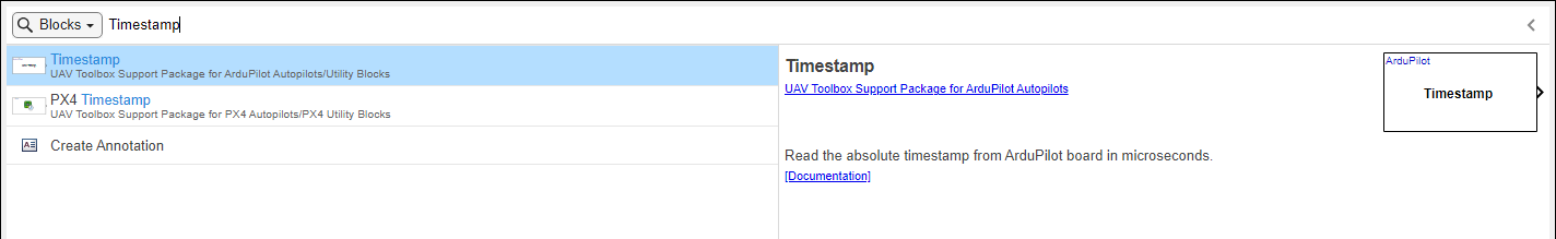
Add the Timestamp block to the model by pressing Enter.
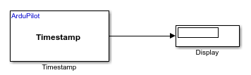
Add a Display block and connect the blocks by creating lines between output ports and input ports. Then, save your model.
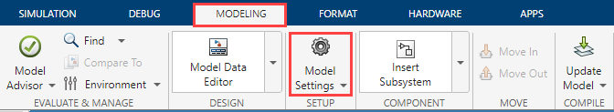
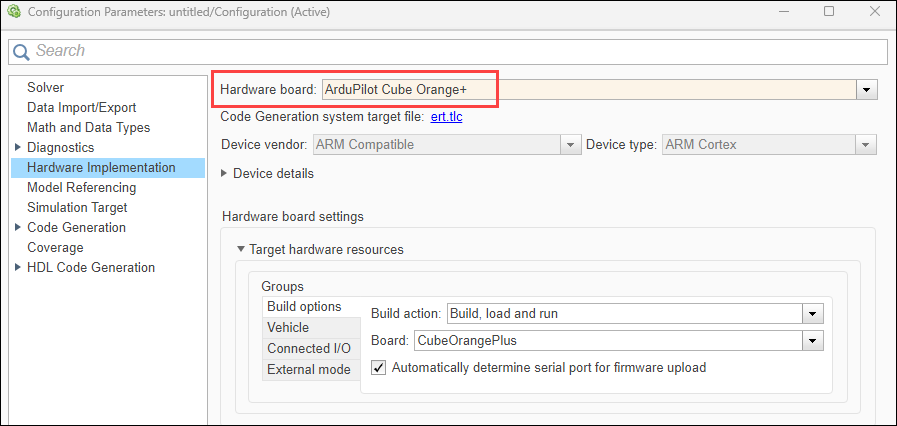
In the Simulink model, go to the Modeling > Model Settings to open Configuration Parameters dialog box.
Click Hardware Implementation and the required ArduPilot hardware board. For example, ArduPilot Cube Orange +
After you have created and configured your Simulink model for use with ArduPilot hardware, you can test, deploy, and validate your algorithms using a variety of supported workflows. The following sections outline the main workflows available: Connected I/O, Build, Deploy & Start, and Monitor and Tune.
Connected I/O
Connected I/O mode enables live data exchange between Simulink and your ArduPilot hardware, allowing you to test and observe your algorithms with real sensor data without fully deploying the model.
Before You Begin:
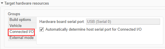
Verify Connected I/O Options:
You can use Connected I/O simulation to communicate with the IO peripherals on the hardware. No modifications are required in this tab. For more information on Connected I/O, see Communicate with Hardware Using Connected I/O.
To use Connected I/O with your ArduPilot hardware, perform these steps:
Set Up the Model.
Add blocks relevant to your algorithm. For example, Attitude Setpoint, Scope.
Configure Connected I/O.

On the Hardware tab, in the in the Mode section, click Connected IO. If you see Run on board selected instead of Connected IO, click on it and choose Connected IO (inputs/outputs mode).
Run the Model.
Click Run with IO.
After the build completes, you will be prompted to reconnect your hardware in order to flash the generated executable. A pop-up window will be displayed with instructions.

Note
The Reconnect ArduPilot Board pop-up is only displayed when a physical ArduPilot board is selected. When using the ArduPilot Host Target, this step is skipped, as no hardware reconnection is required.
Simulink communicates with the hardware, exchanging data in real time.
Use Scope or Display blocks to observe live data.
Use Simulation Pacing (Optional).
To synchronize simulation time with real time, in the Simulation Pacing Options dialog, select Enable pacing to slow down simulation. On enabling, the specified pace gets automatically applied to the simulation. Set the value for Simulation time per wall clock second as
1.Adjust block sample times to match hardware communication rates. For example, 60 ms.
Monitor and Tune
The Monitor and Tune workflow ( External Mode) allows you to monitor signal values and tune parameters on the deployed algorithm in real time, enabling efficient verification and validation on actual hardware.
Before you begin:
Verify External Mode Options:
Verify the options for External mode.
You can use Monitor and Tune (External Mode) action to tune parameters and monitor a Simulink model running on your target hardware. For more information, see Monitor and Tune the Model Running on ArduPilot Autopilots.
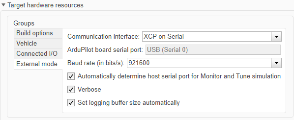
Verify the settings match exactly as shown in the image. Do not modify any of the options.
To use monitor and tune simulation, perform these steps:
Set a value for the Simulation stop time parameter. The default value is
10.0seconds. To run the model for an indefinite period, enterinf.
Configure for signal monitoring and parameter tuning.
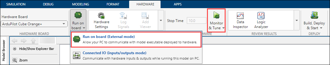
On the Hardware tab, in the in the Mode section, click Run on board and then select Run on board (External mode). If you see Connected IO selected instead of Run on board, click on it and choose Run on board (External mode).
Start Monitor and Tune simulation
Click Monitor & Tune.
Simulink connects to the deployed code, you will be prompted to reconnect your hardware in order to flash the generated executable. A pop-up window will be displayed with instructions.
Note
The Reconnect ArduPilot Board pop-up is only displayed when a physical ArduPilot board is selected. When using the ArduPilot Host Target, this step is skipped, as no hardware reconnection is required.
Observe and Adjust
Use scopes, displays, or dashboards in your model to observe signals.
Adjust parameters as needed and see their effect immediately.
Build, Deploy, & Start
The Build, Deploy and Start workflow allows you to generate code from your Simulink model and deploy it directly to your ArduPilot hardware, enabling real-time execution of your control algorithms.
Deploy the Model
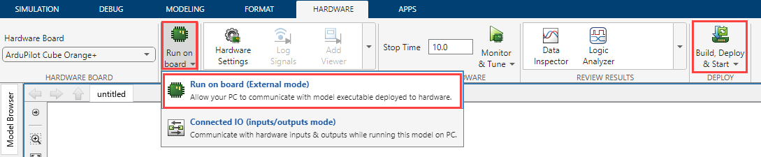
On the Hardware tab, click Build, Deploy & Start.
Simulink will generate code and deploy it to the ArduPilot hardware.
After deployment, the algorithm runs autonomously on the hardware.
After the build completes, you will be prompted to reconnect your hardware in order to flash the generated executable. A pop-up window will be displayed with instructions.