Generate PWM Signals with PX4 PWM Output Block
Prerequisites
If you are new to Simulink, watch the Simulink Quick Start video.
Complete the UAV Toolbox Support Package for PX4 Autopilots Setup and Configuration.
You must install QGroundControl to configure your PX4 Autopilot to run this example.
Required Hardware
PX4® autopilot. This example uses the Pixhawk® 6x autopilot. For a list of supported PX4 autopilots, see Supported PX4 Autopilots.
USB cable.
Optional Hardware
Cathode Ray Oscilloscope (CRO).
Model Overview
Open the px4demo_PWM.slx Simulink model.
open_system("px4demo_PWM.slx");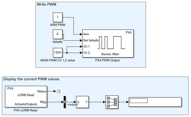
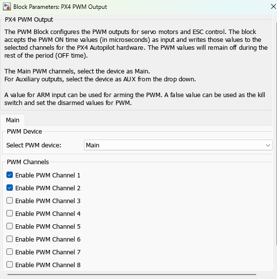
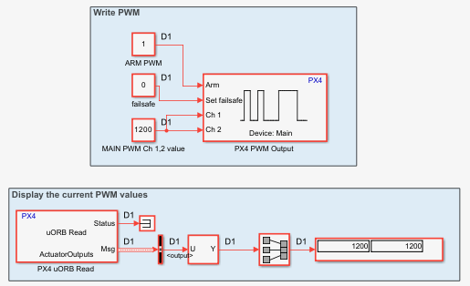
To generate the PWM signal, the px4demo_PWM.slx model uses the PX4 PWM Output block. The block is configured to output PWM signals for the main channels 1 and 2. The Ch port of the PX4 Output PWM block is connected to a constant input of 1200 microseconds. Additionally, the Arm input is connected to a constant boolean value of 1 to arm the actuator output, and the Set failsafe input is connected to a constant boolean value of 0 to disable the failsafe.
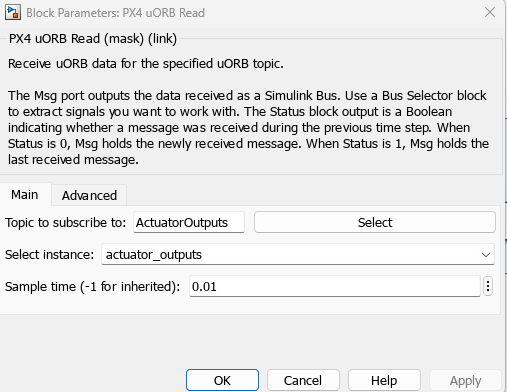
To read the current PWM value that the PX4 autopilot outputs, the px4demo_PWM.slx Simulink model uses a PX4 uORB Read block. The block is configured to subscribe to the actuator_outputs instance of the ActuatorOutputs topic.
Note: The PX4 PWM Output block will be removed in a future release. To update your Simulink models to use the PX4 Actuator Write block instead, see Convert PX4 PWM Output Block to PX4 Actuator Write Block.
Configure Simulink Model
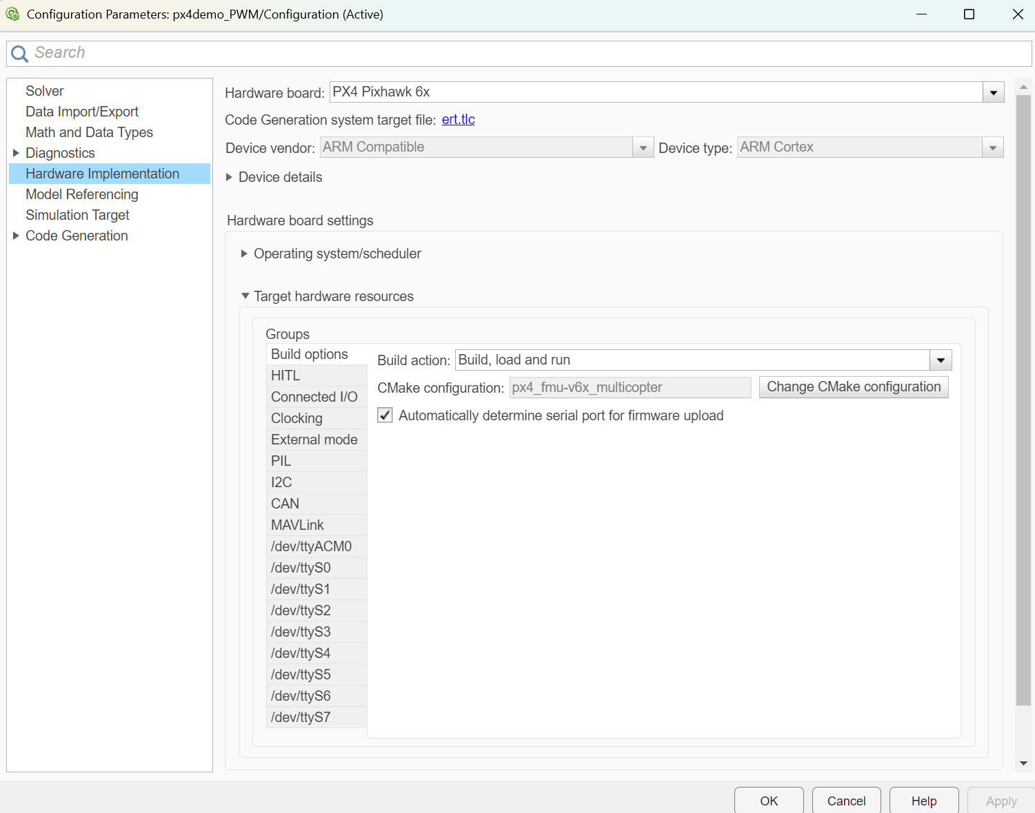
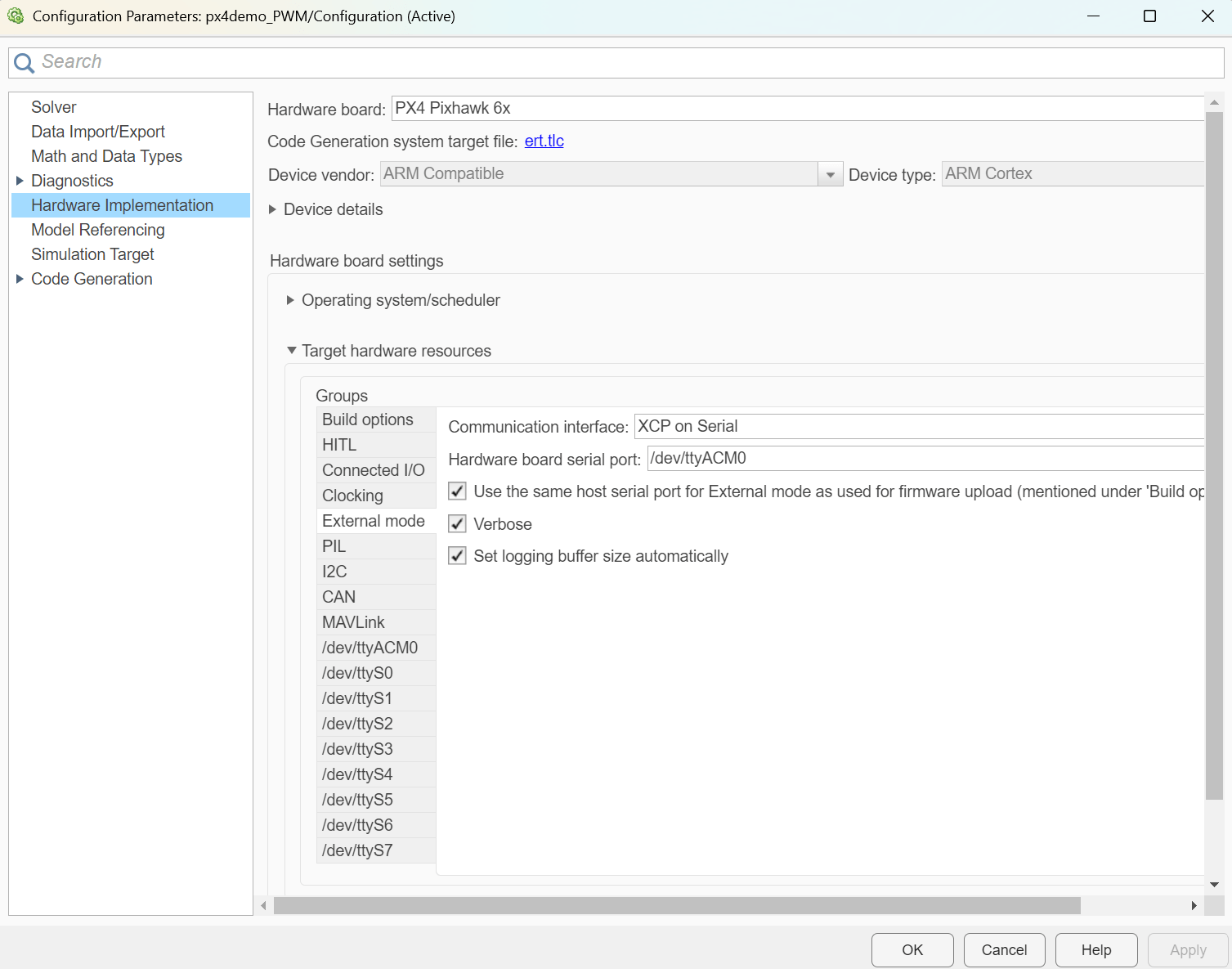
In the px4demo_PWM.slx Simulink model, open the Hardware Implementation tab of the Model Settings, then specify these options:
Set the Hardware board to the PX4 autopilot that you use to run the model. This example uses Pixhawk 6x.
In the Build options pane, set the Build action option to Build, load and run.
Select the Automatically determine serial port for firmware upload option.
In the External mode pane, select the Use the same host serial port for External mode as used for firmware upload option.
Configure PX4 Autopilot in QGroundControl
Connect your PX4 autopilot to your computer and start QGroundControl. After the PX4 autopilot is connected to QGroundControl, click Vehicle Configuration, then click the Actuators tab.
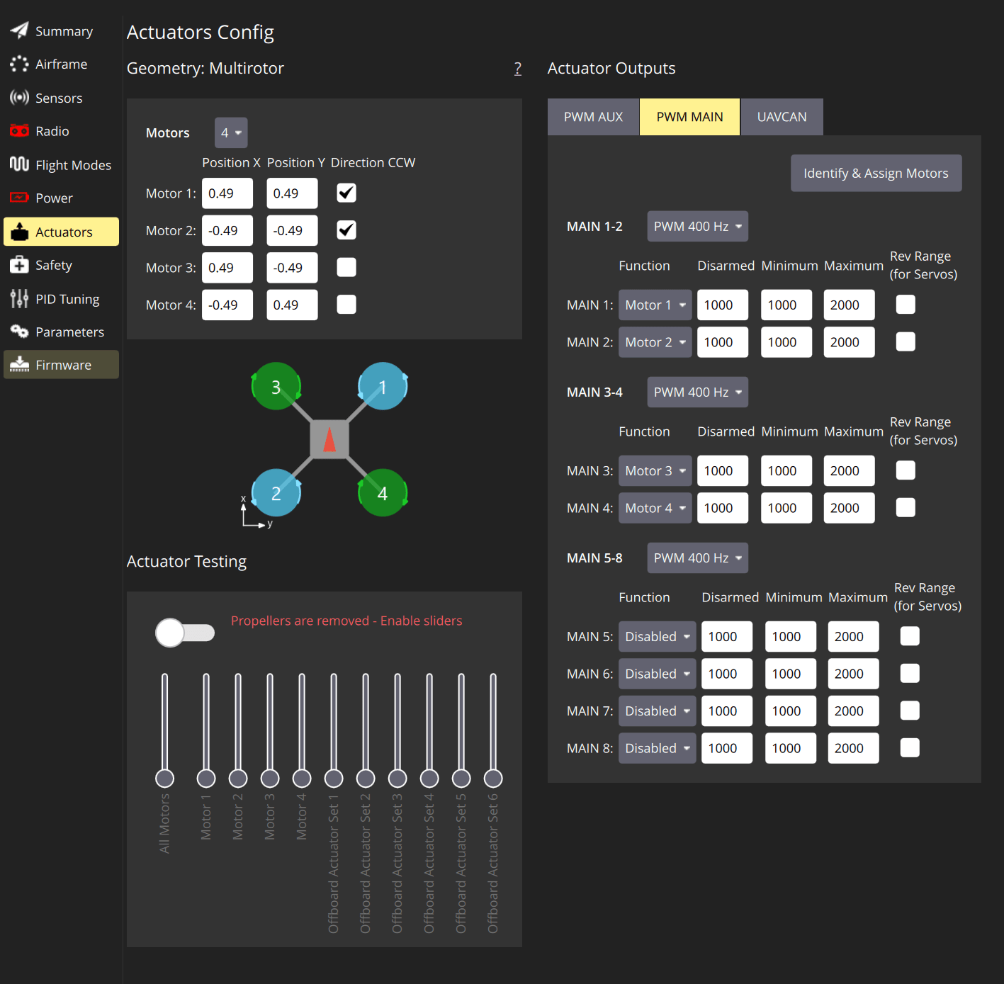
In the Actuators Output section, click the PWM MAIN tab. For channels MAIN 1 to MAIN 4, specify these options:
Function — This option controls the function of each specified MAIN channel, such as to output constant minimum PWM, constant maximum PWM, control motors, landing gear, or other actuator. For this example, choose
Motor 1toMotor 4.Disarmed — This option controls the output PWM on time of the channel when the channel is not armed. For this example, specify an on time of 1000 microseconds.
Minimum — This option controls the minimum output PWM on time of the channel when the channel is armed. For this example, specify an on time of 1000 microseconds.
Maximum — This option controls the maximum output PWM on time of the channel when the channel is armed. For this example, specify an on time of 2000 microseconds.
MAIN 1-2 — This option controls the output PWM frequency for MAIN 1 and MAIN 2 channels. For this example, specify a frequency of 400Hz.
MAIN 3-4 — This option controls the output PWM frequency for MAIN 3 and MAIN 4 channels. For this example, specify a frequency of 400Hz.
Disable the rest of the MAIN channels by specifying the Function option as Disabled.
Run Simulink Model in Connected IO mode
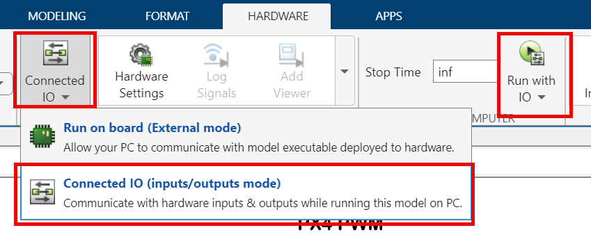
Close the QGroundControl before running the Simulink model. To run the px4demo_PWM.slx model in Connected IO mode:
Click the Hardware tab.
In the Mode pane, click Connected IO (inputs/outputs mode).
Click Run with IO.
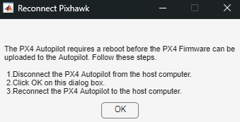
If you run the Simulink model for the first time or use a different PX4 autopilot, Simulink builds the Connected I/O firmware for the PX4 autopilot and prompts you to reconnect the PX4 autopilot. When the dialog box that instructs you to reconnect the PX4 autopilot appears, click OK and then reconnect the PX4 autopilot to your computer.
The PX4 Autopilot now outputs the PWM signals in the main and aux channels, and the Simulink model now displays the PWM values of the MAIN 1 and MAIN 2 channels.
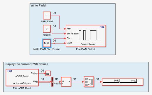
To change the PWM on time value during the simulation, double click the constant block that is connected to the Ch port of the PX4 PWM Output block and specify a new PWM on time value. For example, modify the output of the main channels by double clicking the Main PWM CH 1,2 value block and specify an on time of 1400 microseconds. The PX4 uORB Read block now reads the new PWM on time values, and the scope block displays this value.
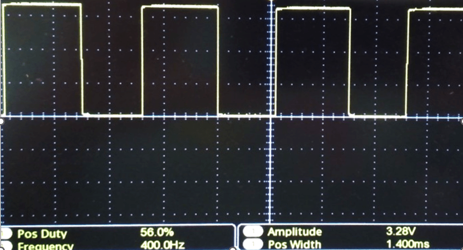
Verify PWM Output with Cathode Ray Oscilloscope
Optionally, you can use a CRO to verify the output signal PWM when the Simulink model is running by connecting a cathode ray oscilloscope (CRO) to the output pin of the PX4 Autopilot corresponding to the channel that you want to test.
This image shows the display of the CRO when connected to the M1 pin of the Pixhawk 6x corresponding to the MAIN 1 channel. The CRO shows that the output signal PWM has an on time of 1.4 ms (1400 microseconds) and a frequency of 400 Hz, consistent with the input that you specify in the Simulink model.