PX4 Autopilot Simulation with UAV Dynamics Modeled and Unreal Engine Flight Visualization
R2026bThis example shows how to use the UAV Toolbox Support Package for PX4® Autopilots to verify a flight controller deployed on a Pixhawk® flight controller in Hardware-in-the-Loop (HITL) simulation with UAV dynamics modeled in Simulink®.
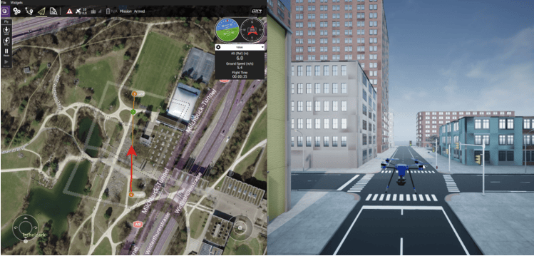
This example also showcases 3D scenario simulation and flight visualization using the Unreal Engine® simulation environment. The simulation environment provides a realistic visualization of the UAV during flight and can be used to evaluate vehicle behavior while running PX4 HITL simulations.
In summary, in this example you,
Configure PX4 Autopilot for HITL simulation.
Deploy a flight controller model to PX4 hardware.
Run UAV dynamics in Simulink.
Visualize the flight in Unreal Engine.
Upload and execute a mission using QGroundControl.
Limitation: The Unreal Engine simulation environment is supported only on Microsoft® Windows® system. If you are using a Linux® system, skip adding the 3D scenario simulation step and still be able to complete this example.
Prerequisites
If you are new to Simulink, watch the Simulink Quick Start video.
Go through the PX4 Hardware-in-the-Loop System Architecture document to understand the physical connections required to setup the Pixhawk and Simulink for HITL Simulation.
Configure and set up Pixhawk in HITL mode. For more information, see Setting Up PX4 Autopilot in Hardware-in-the-Loop (HITL) Mode from QGroundControl.
Setup the PX4 Firmware as mentioned in Set Up PX4 Firmware for Hardware-in-the-Loop (HITL) Simulation. In the Select a PX4 Autopilot and Build Target screen, select any Pixhawk Series board as the PX4 Autopilot board and corresponding build target having
_multicopterkeyword from the drop-down list. This example uses Pixhawk 6x as autopilot board andpx4_fmu-v6x_multicopterbuild target.
Familiarize with the co-simulation framework for UAVs, see Unreal Engine Simulation for Unmanned Aerial Vehicles
It is recommended to understand the Run PX4 Autopilot in Hardware-in-the-Loop (HITL) Simulation with UAV Dynamics in Simulink example.
Required Third-Party Software This example requires this third-party software:
Required Hardware To run this example, you will need the following hardware:
Pixhawk Series flight controller
Micro USB type-B cable
Micro-SD card
Pixhawk serial port connectors
Host PC Configured with GPU Computing Requirements (Parallel Computing Toolbox). It is recommend to use GPU with compute capability of more than 5.
Workflow for PX4 HITL Simulation with Unreal Engine Visualization
This example uses three different Simulink models.
Simulink model for Flight Controller to be deployed on PX4 Autopilot.
Simulink model for UAV Dynamics and sensor simulation.
Simulink model for flight visualization with Unreal Engine Simulation for Unmanned Aerial Vehicles.
To avoid performance degradation in MATLAB®, launch separate MATLAB sessions for the flight controller/UAV dynamics workflow and the optional Unreal Engine visualization model.
In the first session of MATLAB, the Flight Controller is deployed on Autopilot and the UAV Dynamics model will run on host computer communicating with Autopilot.
In the second session of MATLAB, the Simulink model for flight visualization with Unreal Engine Simulation will be running. This can be skipped if you opt to not add the flight visualization.
Step 1: Make Hardware Connections and Set Up the Pixhawk in HITL Mode
1. Connect your Pixhawk board to the host computer using the USB cable.
2. Ensure that you have configured the Pixhawk board in HITL mode as documented in Setting Up PX4 Autopilot in Hardware-in-the-Loop (HITL) Mode from QGroundControl.
3. Ensure that you have setup the PX4 Firmware as mentioned in Set Up PX4 Firmware for Hardware-in-the-Loop (HITL) Simulation.
Step 2: Launch First Session of MATLAB and the MATLAB Project
The support package includes an example MATLAB project having the PX4 flight controller and the UAV to follow the mission set in the QGroundControl (QGC).
1. Open MATLAB.
2. Open the px4demo_HardwareInLoopWithSimulinkPlant MATLAB project.
3. Once the Simulink project is open, click the Project Shortcuts tab on the MATLAB window and click Open Autopilot Controller to launch PX4 Controller named Quadcopter_ControllerWithNavigation.

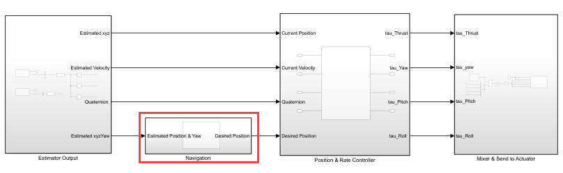
4. Navigate to Navigation subsystem. This is a Implement Structural Variations with Variant Subsystems in a Separate Model Hierarchy (Simulink) with guidanceType as the variant control variable. Define guidanceType = 1 in the global workspace to choose the navigation subsystem for this example.
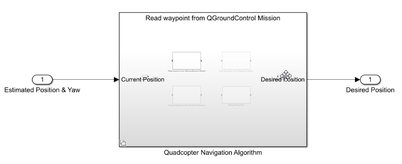
5. In the Project Shortcuts tab, click Open UAV Dynamics to launch the Simulink UAV Dynamics model named UAV_Dynamics_Autopilot_Communication.
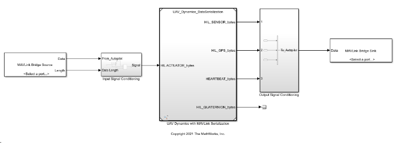
6. Open the Simulink Plant model UAV_Dynamics_Autopilot_Communication and configure the serial port. Select the serial port of the Pixhawk connected to the host computer.
If flight visualization is enabled, add a localhost connection in the MAVLink Bridge Source block and specify port 25000.
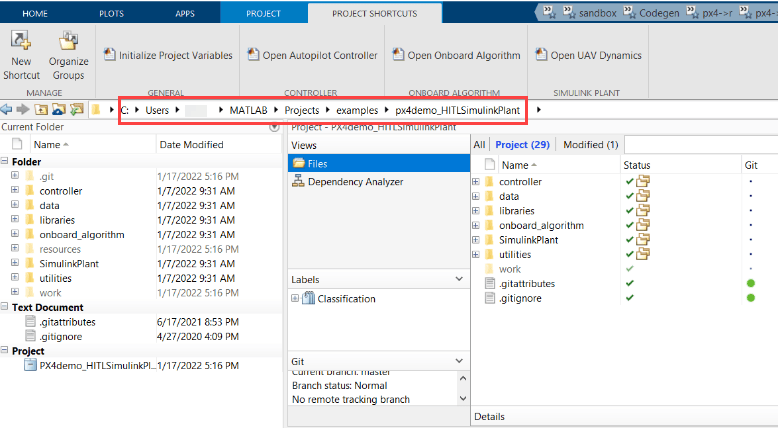
7. Copy the MATLAB Project Path to clipboard.
Step 3: Configure Simulink Controller Model for HITL Mode
1. Follow the instructions mentioned in Configure Simulink Model for Deployment in Hardware-in-the-Loop (HITL) Simulation.
Note: These steps are not required in the pre-configured model. Perform these steps if you have changed the hardware or not using the pre-configured model.
2. Click Build, Deploy & Start from Deploy section of Hardware tab in the Simulink Toolstrip for the Controller model Quadcopter_ControllerWithNavigation.

The code will be generated for the Controller model and the same will be automatically deployed to the Pixhawk board (Pixhawk 6x in this example).
After the deployment is complete, QGroundControl will be automatically launched.
Note: If you are using Ubuntu®, QGC might not launch automatically. To launch QGC, open Terminal and go to the location where QGC is downloaded and run the following command:
./QGroundControl.AppImage
Step 4: Launch Second Session of MATLAB and Open the Flight Visualization Model
Note: Skip this step if you do not opt for flight visualization with PX4 HITL.
1. Open the second instance of the same MATLAB version. In this MATLAB session, The Simulink model for scenario simulation and flight visualization using unreal environment runs.
Ensure that your Host PC is Configured with MATLAB supported GPU (GPU with compute capability of more than 5).
2. Open the px4demo_HardwareInLoopWithSimulinkPlant MATLAB project.
3. Once the Simulink project is open, click the Project Shortcuts tab on the MATLAB window and click Open 3D Visualization with Unreal Engine to launch the onboard model named Unreal_3DVisualization.

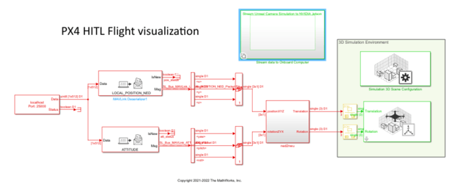
In this model, The MAVLink data from the PX4 Autopilot is received over UDP (port : 25000) and is used to decode the position and attitude data of the UAV. After coordinate conversion, it is then passed to the Simulation 3D UAV Vehicle block for flight visualization.
4. On the Simulation tab, click Run to simulate the model. Once the model start running, you will see the Unreal simulation environment getting launched. A sample screen is shown below.

Step 5: Run the UAV Dynamics Model, Upload Mission from QGroundControl and Fly the UAV
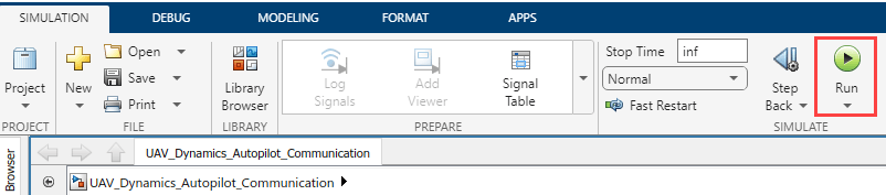
1. In the Simulink toolstrip of the Plant model (UAV_Dynamics_Autopilot_Communication), on the Simulation tab, click Run to simulate the model. Once the plant model starts running, in QGroundControl connection will be established.
2. In the Parameters tab, set the COM_DISARM_PRFLT parameter value to -1.
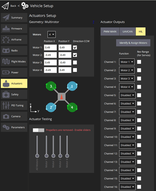
3. Configure the actuators in QGC. For more information, see Configure and Assign Actuators in QGroundControl.
4. In the QGC, navigate to the Plan View.
5. Create a mission. For information on creating a mission, see Plan View.
After you create a mission, it is visible in QGC.
6. Click Upload button in the QGC interface to upload the mission from QGroundControl.
7. Navigate to Fly View to view the uploaded mission.
8. Start the Mission in QGC. The UAV should follow the mission path.
9. Observe the flight visualization in the Unreal Engine.
Troubleshooting
While Simulating the visualization model in Step 4, you might get any STD exception errors such as, "some module could not be found".
Change the compiler to Microsoft Visual C++ 2019 using mex -setup c++ command to fix the issue.
When you start the Mission the vehicle is not taking off.
Firstly, verify if you are receiving the 'TRAJECTORY_REPRESENTATION_WAYPOINTS' message in the Onboard model. If the 'isNew' output for 'TRAJECTORY_REPRESENTATION_WAYPOINTS' in the MAVLink Deserializer Block related to is always false, it indicates that the message is not being received.

