Communicate with Hardware Using Connected I/O
You can use Connected I/O simulation to communicate with the IO peripherals on the hardware.
Simulation with Connected I/O is an intermediate step in the Model-Based Design workflow that bridges the gap between simulation and code generation by enabling Simulink® to communicate with the hardware before deploying the model on hardware. Connected I/O enables you to modify your model design and monitor the effect of the modified design using the peripheral data from the hardware in a near real-time environment. You are not required to deploy the model on the hardware to monitor the effect of the modified design, which accelerates the simulation process. This Simulink (software) - PX4® (hardware) interaction is available only when you run the model in Connected I/O mode.
Note
Connected I/O is not based on Simulink code generation, and hence Embedded Coder® license is not required to use Connected I/O simulation.
These sections explain:
Supported PX4 Boards and Blocks with Connected I/O
The Connected I/O described here applies to the UAV Toolbox Support Package for PX4 Autopilots on these PX4 boards and blocks:
Source blocks: Without Connected I/O, these source blocks output zero during simulation. With Connected I/O, these blocks read data from the peripherals of the hardware during Connected I/O simulation.
Sink blocks: Without Connected I/O, these sink blocks do not have any role during simulation. With Connected I/O, these blocks write data to the peripherals of the hardware during Connected I/O simulation.
All PX4 boards and blocks support Connected I/O. For more information, see:
How Connected I/O Works
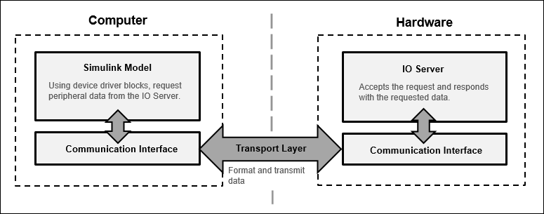
Connected I/O creates a communication interface that enables the Simulink model and the IO Server to communicate with each other. The Simulink model resides in your computer, and the IO Server is an engine on the hardware that contains all the peripheral functions. The transport layer formats and transmits the data using the communication interface.
This diagram shows the connection that the Connected I/O creates between your computer and the hardware.

When you simulate a Simulink model in Connected I/O mode:
The device driver block (for example, PX4 uORB Read block) in the model request sensor data from the IO Server.
The IO Server accepts the request and responds with the requested data. You can use any Simulink sink or dashboard block to view the received data. Using the peripheral data received, you can verify that your model design meets the requirements.
If necessary, you can modify the design by adding, removing, or replacing any block in the Simulink model.
After the model is modified, resimulate the model in Connected I/O mode. During simulation, the data request from the model is communicated to the hardware. You can continue to modify and simulate the model until the expected behavior is achieved.
Note
The communication in Connected I/O is an on-demand process. The hardware sends data only when receiving a data request from the Simulink model.
You do not have to build, deploy, and run the model on the hardware to monitor the effects of your changes in your model design.
Connected I/O in Model-Based Design
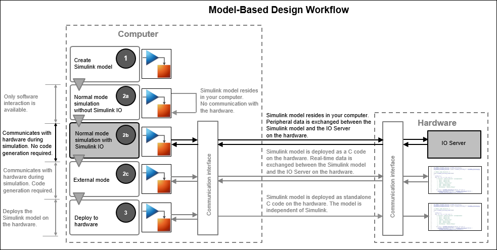
When you simulate a model in Normal mode without Connected I/O, Simulink does not communicate with the hardware. Simulink communicates with the hardware only when the code is generated and the model is deployed on the hardware in External mode. Connected I/O simulation is an intermediate step in the model-based design workflow that bridges the gap between simulation and code generation by enabling Simulink to communicate with the hardware before deploying the model on the hardware.
This Model-Based Design Workflow diagram displays a model-based workflow:
Create a Simulink model.
Simulate the model in:
Simulation without Connected I/O: There is no hardware interaction and no code generation.
Simulation with Connected I/O: The model communicates with the hardware. There is no code generation.
Monitor & Tune (External mode): The model is deployed on the hardware and generates code.
Deploy the model to the hardware.

How Connected I/O Differs from Monitor & Tune (External Mode)
Connected I/O and Monitor & Tune (External Mode) both enable you to communicate with the hardware during simulation. However, you use Connected I/O and Monitor & Tune for different purposes. The table shows the actions that you can perform with each mode.
| Action | External Mode | Connected I/O |
|---|---|---|
| Obtain real-time data | You can obtain real-time data with Monitor & Tune. | You can obtain only non real-time data with Connected I/O. |
| Time required to start simulation | 1-2 minutes | Few seconds |
| Code generation | Code is generated on the hardware. Embedded Coder license is required. | No code is generated. Embedded Coder license is not required. |
When to Use Connected I/O
Connected I/O must be used primarily as a Sensor/Actuator block characterization which enables a fast way to get started with a block to understand its outputs/inputs. In Connected I/O every block needs to communicate to the PX4 boards and thus there is a specific minimum time required for a block execution. If the sample time specified is smaller than this block execution time, the block cannot run at the specified sample time during connected I/O simulation. This makes Connected I/O simulation not suitable for designing closed loop controllers and systems with dynamic feedback, where blocks must run at much higher rate.
Note
Connected I/O simulation is not ideal for application involving a continuous / dynamic feedback from the plant.
Run Simulink Model in Connected I/O
To simulate a model in Connected I/O during Normal mode simulation, perform these steps:
Open a Simulink model.
In the Modeling tab, select Model Settings.
In the Configuration Parameters dialog box, select Hardware Implementation from the left pane and select the target hardware in the Hardware board parameter.
On the Hardware tab of the model, in the Mode section, select
Connected
                                IO
and then click Run with IO.
Additionally, you can change the rate of simulation by enabling the simulation pacing. For more information, see Simulation Pacing Options (Simulink).

See Also
Getting Started with Connected IO for PX4 Host Target | Getting Started with Connected IO for PX4 Autopilot