Forward Collision Warning Application with CAN FD and TCP/IP
This example shows how to execute a forward collision warning (FCW) application with sensor and vision data replayed live via CAN FD and TCP/IP protocols. Recorded data from a sensor suite mounted on a test vehicle are replayed live as if they were coming through the network interfaces of the vehicle. Vehicle Network Toolbox™ and Instrument Control Toolbox™ provide these interfaces. This setup is used to test an FCW system developed using features from Automated Driving Toolbox™. For assistance with the design and development of actual FCW algorithms, refer to the example Forward Collision Warning Using Sensor Fusion (Automated Driving Toolbox).
System Configuration
This example uses virtual CAN FD channels from Vector. These virtual device channels are available with the installation of the Vector Driver Setup package from www.vector.com.
This example has two primary components:
Transmitter: Sends the sensor and vision data via CAN FD and TCP/IP. This portion represents a sample vehicle environment. It replays prerecorded data as if it were a live vehicle.
Receiver: Collects all the data and executes the FCW algorithm and visualizations. This portion represents the application component.
To execute the example, the transmitter and receiver portions run from separate sessions of MATLAB®. This replicates the data source existing outside the MATLAB session serving as the development tool. Furthermore, this example allows you to run the FCW application in multiple execution modes (interpreted and MEX) with different performance characteristics.

Generate Data
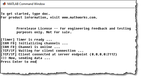
The transmitting application executes via the helperStartTransmitter function. It launches a separate MATLAB process to run outside of the current MATLAB session. The transmitter initializes itself and begins sending sensor and vision data automatically. To run the transmitter, use the system command.
system('matlab -nodesktop -nosplash -r helperStartTransmitter &')

Execute Forward Collision Warning System (Interpreted Mode)
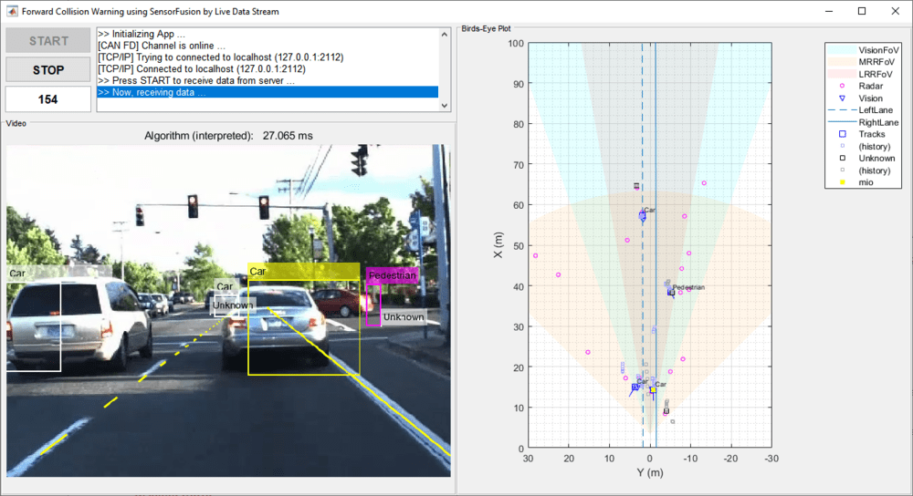
To open the receiving FCW application, execute the helperStartReceiver function. You can click START to begin data reception, processing, and visualization. You can explore the helperStartReceiver function to see how the Vehicle Network Toolbox CAN FD functions, Instrument Control Toolbox TCP/IP functions, and Automated Driving Toolbox capabilities are used in concert with one another.
helperStartReceiver('interpreted')

Review Results
When ready, stop the transmitter application using the close window button on its command window. Click STOP on the receiving FCW application, and then close its window as well.
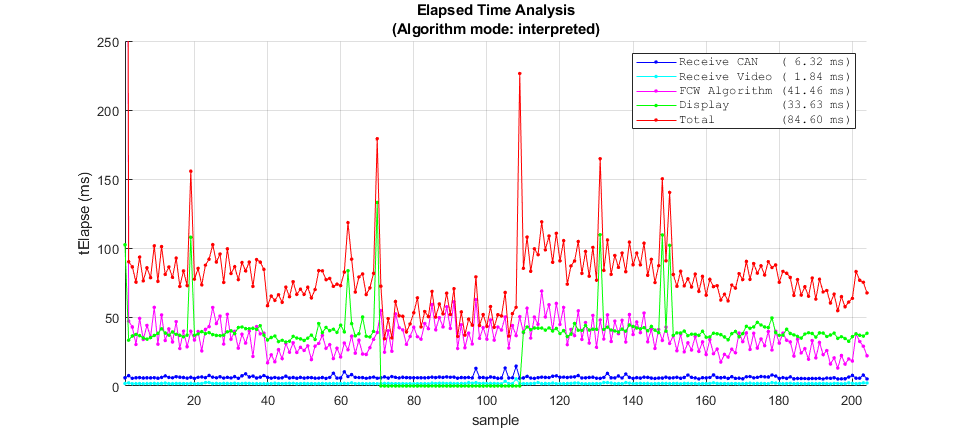
When the receiving FCW application is stopped, a plot appears detailing performance characteristics of the application. It shows time spent receiving data, processing the FCW algorithm, and performing visualizations. Benchmarking is useful to show parts of the setup that need performance improvement. It is clear that a significant portion of time is spent executing the FCW algorithm. In the next section, explore code generation as a strategy to improve performance.

Execute Forward Collision Warning System (MEX Mode)
If faster performance is a requirement in your workflow, you can use MATLAB Coder™ to generate and compile MATLAB code as MEX code. To build this example as MEX code, use the helperGenerateCode function. The build will compile the FCW application into a MEX function directly callable within MATLAB.
helperGenerateCode('mex')
Restart the transmitter application.
system('matlab -nodesktop -nosplash -r helperStartTransmitter &')
The receiving FCW application can also be restarted. This time with an input argument to use the MEX compiled code built in the prior step.
helperStartReceiver('mex')
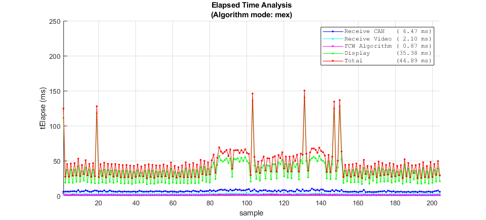
When ready, stop and close the transmitter and receiving FCW application. Comparing the time plot for MEX execution to the interpreted mode plot, you can see the performance improvement for the FCW algorithm.

Use Physical Hardware and Multiple Computers
The example uses a single computer to simulate the entire system with virtual connectivity. As such, its performance is meant as an approximation. You can also execute this example using two computers (one as transmitter, one as receiver). This would represent more of a real live data scenario. To achieve this, you can make simple modifications to the example code.
Changing the CAN FD communication from virtual to physical devices requires editing the transmission and reception code to invoke canChannel using a hardware device instead of the virtual channels. You may also need to modify the call to configBusSpeed depending on the capabilities of the hardware. These calls are found in the helperStartReceiver and dataTransmitter functions of the example.
Changing TCP/IP communication for multiple computers requires adjusting the TCP/IP address of the transmitter from local host (127.0.0.1) to a static value (192.168.1.2 recommended). This address is set first on the host transmitting computer. After, modify the tcpipAddr variable in the helperStartReceiver function to match.
Once configured and connected physically, you can run the transmitter application on one computer and the FCW application on the other.