Main Content

wlanPreEHTChannelEstimate

Channel estimation using pre-EHT fields

Since R2023b

Description

chEst = wlanPreEHTChannelEstimate(demodSym,chEstLLTF,cbw) returns the channel estimate at the legacy signal field (L-SIG) using the demodulated L-SIG field symbols, demodSym, and the channel estimate at the legacy long training field (L-LTF), chEstLLTF. The channel bandwidth is specified in cbw. For more information about these fields, see L-SIG and L-LTF.

example

chEst = wlanPreEHTChannelEstimate(___,span) specifies the span of a moving-average filter in addition to the input arguments in the previous syntax. The function uses this filter to perform frequency smoothing.

example

Examples

collapse all

Create an EHT MU configuration object with a channel bandwidth of 20 MHz. Generate a time-domain waveform for the configuration.

cfg = wlanEHTMUConfig("CBW20");
cbw = cfg.ChannelBandwidth;
txSig = wlanWaveformGenerator([1;0;0;1],cfg);

Pass the signal through an AWGN channel with a signal-to-noise ratio of 20 dB.

rxSig = awgn(txSig,20);

Get the field indices of the configuration, demodulate the L-LTF, and perform L-LTF channel estimation.

ind = wlanFieldIndices(cfg);
demodSigLLTF = wlanEHTDemodulate(rxSig(ind.LLTF(1):ind.LLTF(2),:),"L-LTF",cfg);
chEstLLTF = wlanLLTFChannelEstimate(demodSigLLTF,cbw);

Demodulate the L-SIG and RL-SIG fields.

demodSigLSIG = wlanEHTDemodulate(rxSig(ind.LSIG(1):ind.RLSIG(2),:),"L-SIG",cfg);

Using a frequency smoothing span of 5, perform the full channel estimation.

est = wlanPreHEChannelEstimate(demodSigLSIG,chEstLLTF,cbw,5);

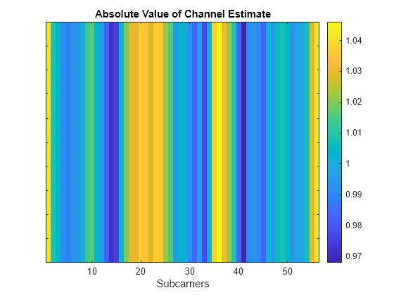
Display the absolute value of the channel estimate.

imagesc(abs(est.'))
title("Absolute Value of Channel Estimate")
xlabel("Subcarriers")
set(gca,YTickLabels=[])
colorbar

Figure contains an axes object. The axes object with title Absolute Value of Channel Estimate, xlabel Subcarriers contains an object of type image.

Input Arguments

collapse all

Demodulated L-SIG field symbols, specified as an NST-by-NSYM-by-NR array. NST is the number of occupied subcarriers. NSYM is the number of OFDM symbols in the L-SIG and repeated legacy signal (RL-SIG) fields. NR is the number of receive antennas.

Data Types: single | double
Complex Number Support: Yes

Channel estimate at the legacy long training field, specified as an NST-by-1-by-NR array. NST is the number of occupied subcarriers and NR is the number of receive antennas.

Data Types: single | double
Complex Number Support: Yes

Channel bandwidth, specified as one of these values.

  • "CBW20" — Channel bandwidth of 20 MHz

  • "CBW40" — Channel bandwidth of 40 MHz

  • "CBW80" — Channel bandwidth of 80 MHz

  • "CBW160" — Channel bandwidth of 160 MHz

  • "CBW320" — Channel bandwidth of 320 MHz

Data Types: char | string

Span of the frequency smoothing filter, specified as a positive odd integer and expressed as a number of subcarriers. The function applies frequency smoothing only when span is greater than one. For more information on when to specify this input, see Frequency Smoothing.

Data Types: double

Output Arguments

collapse all

Channel estimate at all data and pilot subcarriers, returned as an NST-by-1-by-NR array. NST is the number of occupied subcarriers and NR is the number of receive antennas. The output includes the channel estimates for the extra four subcarriers per each 20 MHz subchannel in the L-SIG field.

More About

collapse all

L-SIG

The L-SIG is the third field of the 802.11™ OFDM PLCP legacy preamble. This field is a component of EHT, HE, VHT, HT, and non-HT PPDUs. It consists of 24 bits that contain rate, length, and parity information. The L-SIG field uses BPSK modulation with rate 1/2 binary convolutional coding (BCC).

The L-SIG consists of one OFDM symbol with a duration that varies with channel bandwidth.

Channel Bandwidth (MHz)Subcarrier Frequency Spacing, ΔF (kHz)Fast Fourier Transform (FFT) Period (TFFT = 1 / ΔF)Guard Interval (GI) Duration (TGI = TFFT / 4)L-SIG Duration (TSIGNAL = TGI + TFFT)
20, 40, 80, 160, and 320312.53.2 μs0.8 μs4 μs
10156.256.4 μs1.6 μs8 μs
578.12512.8 μs3.2 μs16 μs

The L-SIG contains packet information for the received configuration.

Packet information in the L-SIG

  • Bits 0 through 3 specify the data rate (modulation and coding rate) for the non-HT format.

    Rate (Bits 0–3)Modulation

    Coding Rate (R)

    Data Rate (Mb/s)
    20 MHz Channel Bandwidth10 MHz Channel Bandwidth5 MHz Channel Bandwidth
    1101BPSK1/2631.5
    1111BPSK3/494.52.25
    0101QPSK1/21263
    0111QPSK3/41894.5
    100116-QAM1/224126
    101116-QAM3/436189
    000164-QAM2/3482412
    001164-QAM3/4542713.5

    For HT and VHT formats, the L-SIG rate bits are set to '1 1 0 1'. Data rate information for HT and VHT formats is signaled in format-specific signaling fields.

  • Bit 4 is reserved for future use.

  • Bits 5 through 16:

    • For non-HT formats, specify the data length (amount of data transmitted in octets) as described in Table 17-1 and Section 10.27.4 IEEE® Std 802.11-2020.

    • For HT-mixed formats, specify the transmission time as described in Sections 19.3.9.3.5 and 10.27.4 of IEEE Std 802.11-2020.

    • For VHT formats, specify the transmission time as described in Section 21.3.8.2.4 of IEEE Std 802.11-2020.

  • Bit 17 has the even parity of bits 0 through 16.

  • Bits 18 through 23 contain all zeros for the signal tail bits.

Note

Signaling fields added for HT (wlanHTSIG) and VHT (wlanVHTSIGA, wlanVHTSIGB) formats provide data rate and configuration information for those formats.

  • For the HT-mixed format, Section 19.3.9.4.3 of IEEE Std 802.11-2020 describes HT-SIG bit settings.

  • For the VHT format, Sections 21.3.8.3.3 and 21.3.8.3.6 of IEEE Std 802.11-2020 describe bit settings for the VHT-SIG-A and VHT-SIG-B fields, respectively.

RL-SIG

The RL-SIG is a repeat of the L-SIG to distinguish an HE or EHT PPDU from a non-HT, HT, or VHT PPDU.

L-LTF

The L-LTF is the second field in the 802.11 OFDM PLCP legacy preamble. The L-LTF is a component of EHT, HE, VHT, HT, and non-HT PPDUs.

Channel estimation, fine frequency offset estimation, and fine symbol timing offset estimation rely on the L-LTF.

The L-LTF is composed of a cyclic prefix (CP) followed by two identical long training symbols (C1 and C2). The CP consists of the second half of the long training symbol.

The L-LTF duration varies with channel bandwidth.

Channel Bandwidth (MHz)Subcarrier Frequency Spacing ΔF (kHz)Fast Fourier Transform (FFT) Period (TFFT = 1 / ΔF)Cyclic Prefix or Training Symbol Guard Interval (GI2) Duration (TGI2 = TFFT / 2)L-LTF Duration (TLONG = TGI2 + 2 × TFFT)
20, 40, 80, 160, and 320312.53.2 μs1.6 μs8 μs
10156.256.4 μs3.2 μs16 μs
578.12512.8 μs6.4 μs32 μs

Frequency Smoothing

Frequency smoothing can improve channel estimation by averaging out noise.

Frequency smoothing is recommended only for cases in which a single transmit antenna is used. Frequency smoothing consists of applying a moving-average filter that spans multiple adjacent subcarriers. Channel conditions dictate whether frequency smoothing is beneficial.

  • If adjacent subcarriers are highly correlated, frequency smoothing results in significant noise reduction.

  • In a highly frequency-selective channel, smoothing can degrade the quality of the channel estimate.

References

[1] IEEE Std 802.11-2020 (Revision of IEEE Std 802.11-2016). “Part 11: Wireless LAN Medium Access Control (MAC) and Physical Layer (PHY) Specifications.” IEEE Standard for Information Technology — Telecommunications and Information Exchange between Systems — Local and Metropolitan Area Networks — Specific Requirements.

[2] IEEE Std 802.11ax™-2021 (Amendment to IEEE Std 802.11-2020). “Part 11: Wireless LAN Medium Access Control (MAC) and Physical Layer (PHY) Specifications. Amendment 1: Enhancements for High Efficiency WLAN.” IEEE Standard for Information Technology — Telecommunications and Information Exchange between Systems. Local and Metropolitan Area Networks — Specific Requirements.

Extended Capabilities

C/C++ Code Generation
Generate C and C++ code using MATLAB® Coder™.

Version History

Introduced in R2023b