Contenido principal

beamwidth

R2026b

Calculate Half-Power Beamwidth (HPBW) of AI-based antenna

Since R2025a

    Description

    beamwidth(aiant,frequency) calculates the half-power beamwidth of an AI-based antenna object at the specified frequency and displays a visualization of the far-field analysis, including:

    • Beamwidth spans in the principal planes

    • Peak radiation direction

    • Supporting geometric context

    The calculated beamwidth value is also displayed in the output.

    hpbw = beamwidth(aiant,frequency) calculates and returns the half-power beamwidth of an AI-based antenna object at the specified frequency. Half-power beamwidth is the angular separation at which the magnitude of the directivity pattern decreases by 3 dB from the peak of the main beam.

    [hpbw,angles,plane] = beamwidth(aiant,frequency) calculates and returns the half-power beamwidth, its lower and upper angular points, and plane of calculation of an AI-based antenna object at the specified frequency.

    example

    Examples

    collapse all

    This example shows how to create an AI-based microstrip patch antenna operating at 1.67 GHz and calculate its beamwidth.

    Use the design function with the ForAI argument set to true to create an AI-based microstrip patch antenna.

    pAI = design(patchMicrostrip,1.67e9,ForAI=true)
    pAI = 
      AIAntenna with properties:
    
       Antenna Info
                   AntennaType: 'patchMicrostrip'
        InitialDesignFrequency: 1.6700e+09
    
       Tunable Parameters
                        Length: 0.0862
                         Width: 0.1122
                        Height: 0.0018
    
    Show read-only properties


    Explore the design space by changing its length and width with values within the tunable range of these properties. You can get the tunable range of a property by using tunableRanges function on the AI-based antenna object.

    pAI.Length = 0.0855;
    pAI.Width = 0.113;

    Calculate half-power beamwidth of the antenna, its lower and upper angular points, and get the information on plane of calculation.

    [hpbw,angles,plane] = beamwidth(pAI,1.67e9)
    hpbw = 2×1
    
       56.6456
       61.1775
    
    
    angles = 2×2
    
       60.1510  116.7966
       58.9239  120.1013
    
    
    plane = 2×3 table
           Plane       Slice    SliceValue
        ___________    _____    __________
    
        "Elevation"    "Az"          0    
        "Elevation"    "Az"         90    


    Create an AI-based rectangular microstrip patch antenna operating at 1.67 GHz.

    f0 = 1.67e9;
    pAI = design(patchMicrostrip,f0,ForAI=true);

    Modify the length and width of the antenna.

    pAI.Length = 0.0855;
    pAI.Width = 0.113;

    Calculate and visualize the beamwidth at 1.67 GHz.

    beamwidth(pAI,f0)
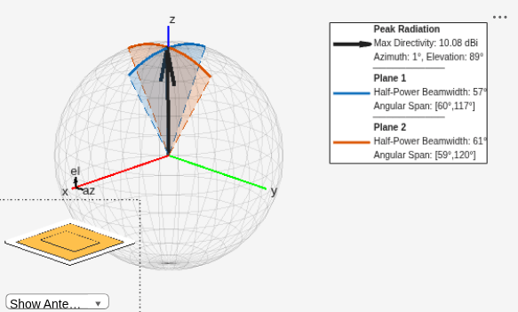
    Figure contains 2 axes objects and another object of type uicontrol. Axes object 1 contains 5 objects of type patch, surface. Hidden axes object 2 contains 21 objects of type line, patch, quiver, scatter, surface, text.

    ans = 2×1
    
       56.6456
       61.1775


    Input Arguments

    collapse all

    AI-based antenna, specified as an AIAntenna object created using the design function.

    Example: aiant = design(patchMicrostrip,1.67e9,ForAI=true); hpbw = beamwidth(aiant,1.67e9) calculates and returns the half-power beamwidth of AI-based microstrip patch antenna at 1.67 GHz.

    Frequency to calculate beamwidth, specified as a scalar in Hertz.

    Example: 70e6

    Data Types: double

    Output Arguments

    collapse all

    Half-power beamwidth of AI-based antenna, returned as a 2-by-1 vector in degrees. The rows of this vector correspond to planes 1 and 2 respectively.

    Example: [56; 60]

    Data Types: double

    Angular points encompassing the half-power region of the main beam in the azimuth or elevation plane, returned as a 2-by-2 matrix in degrees. The rows of this matrix correspond to planes 1 and 2 respectively.

    Example: [60 116; 60 120]

    Data Types: double

    Planes used for beamwidth calculation, returned as 2-by-3 table. These planes are defined by the azimuth or elevation slices.

    Beamwidth is calculated along the horizontal and vertical cross-sections of an ideal radiation pattern of the antenna.

    • For patch antennas, the beamwidth is calculated along:

      • The elevation plane at an azimuth angle of 0 degrees.

      • The elevation plane at an azimuth angle of 90 degrees.

    • For dipole, waveguide, and horn antennas, the beamwidth is calculated along:

      • The elevation plane at an azimuth angle of 0 degrees.

      • The azimuth plane at an elevation angle of 0 degrees.

    Data Types: table

    Version History

    Introduced in R2025a

    expand all

    See Also

    Objects

    Functions