Configure AUTOSAR Adaptive Software Component Service Mappings
R2026bIn Simulink®, you can use the Service Mappings Editor, the Property Inspector, and the AUTOSAR Dictionary to configure properties of AUTOSAR Adaptive software component elements. For more information, see Configure AUTOSAR Adaptive Service Interface Properties.
Use the Service Mappings editor and the Property Inspector to map model elements to services, and to configure their communication, execution, code, or calibration properties, depending on the type of model element you are configuring.
Before R2026b, you used the Code Mappings editor (or programmatic interfaces) to explicitly map Simulink inports, outports, and functions to AUTOSAR Adaptive elements. Starting in R2026b, you use the Service Mappings editor to explicitly map Simulink elements to AUTOSAR elements that are configured for persistency and measurement services. Receivers, senders, clients, and servers are modeled directly in Simulink, and their configured service properties map implicitly to AUTOSAR Adaptive elements and service implementations.
To map model elements to services and to configure their properties, the Service Mappings editor contains a set of tables organized into tabs. Each tab represents a category of model elements that can be mapped to services, and each table entry represents a mapped model element.
Use the Receivers, Senders, Clients, and Servers tabs to map model ports and port elements to communication services.
Use the Parameters tab to map parameters and variant controls to tuning services.
Use the Measurements tab to map signals, states, and data stores to measurement services.
The mapping properties you configure are reflected in the algorithmic code and in the generated service implementation code, and in the exported ARXML descriptions that are compliant with the AUTOSAR Adaptive Platform.
Map Model Ports and Port Elements to Communication Services
To configure the mapping properties of model ports and port elements use this workflow:
Open the example model
adaptive_ActuatorSWC, for which AUTOSAR system target fileautosar_adaptive.tlcis selected:openExample("adaptive_ActuatorSWC")Open the AUTOSAR Component Designer app. In the Simulink Toolstrip, on the Apps tab select AUTOSAR Component Designer.
Tip
If a model has not yet been mapped to the AUTOSAR software component, the AUTOSAR Component Quick Start opens when you select the AUTOSAR Component Designer app in the gallery. In the Quick Start, select the AUTOSAR Adaptive Platform and work through the procedure. When you are done, click Finish to complete the mapping and to add the AUTOSAR tab to the Simulink Toolstrip. For more information, see Create Mapped AUTOSAR Component with Quick Start.
The model
adaptive_ActuatorSWCis already configured as an AUTOSAR Adaptive software component, so the AUTOSAR tab is added to the Simulink Toolstrip without opening the Quick Start.In the Simulink Toolstrip, navigate to the AUTOSAR tab. Then, in the Prepare section, click Service Mappings to open the Service Mappings editor.
The Service Mappings editor opens as a tab at the bottom of the model canvas. If it is minimized, double-click it to expand it.
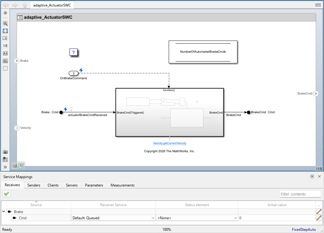
The Service Mappings editor provides access to service mapping information, with batch editing, element filtering, and model element traceability.
In this example, you use the Service Mappings editor to perform these actions:
Configure service properties for AUTOSAR Adaptive sender-receiver communication.
Map model parameters to AUTOSAR parameter tuning services.
Use the Filter Content field in the upper-right corner of the Service Mappings editor to selectively display entries that contain specific text.
Tip
You can select the value of multiple elements simultaneously, updating the value after selecting multiple rows.
After mapping model elements, click the validation button
 at the top of the Service Mappings editor to validate the AUTOSAR
Adaptive software component service properties. If errors are reported, address them and
then retry validation.
at the top of the Service Mappings editor to validate the AUTOSAR
Adaptive software component service properties. If errors are reported, address them and
then retry validation.
Configure Sender-Receiver Communication with Service Mappings
Event-based data communication between AUTOSAR Adaptive software components occurs when a provider component sends events through provided ports, and a consumer component receives those events through required ports. In Simulink, you model event-based data communication as sender-receiver communication by using In Bus Element blocks to receive events and Out Bus Element blocks to send events. Each required and provided port corresponds to a data port on the software component boundary. Use the Receivers and Senders tabs of the Service Mappings editor to map the port elements to services.
On the Receivers tab, you can set these properties for each port
element: Receiver Service, Status Element, and
Initial Value. Additionally, you can click on the pencil icon
 at the end of the entry to open the dialog box for additional properties where
you can configure these service properties: Queue capacity,
Timeout, and Sample time (which is only
applicable for rate based models). For more information, see Model AUTOSAR Adaptive Sender-Receiver Communication and Execution.
at the end of the entry to open the dialog box for additional properties where
you can configure these service properties: Queue capacity,
Timeout, and Sample time (which is only
applicable for rate based models). For more information, see Model AUTOSAR Adaptive Sender-Receiver Communication and Execution.
By default, each In Bus Element block maps to a separate AUTOSAR Adaptive
Required port with the same name as the block. This includes both blocks that are mapped to
receiver services and blocks that are mapped to client services. To combine the events of a
block that is mapped to receiver services with the methods of a block that is mapped to
client services onto a shared required port, specify the same required port as the
Service port of both blocks. To learn about the AUTOSAR dictionary
and required ports in it, see Define AUTOSAR Adaptive Software Component Ports and Interfaces. For example, to
specify the Service port of the Brake
In Bus Element block, use one of these methods:
Select the In Bus Element block in the model canvas and open the Property Inspector. Make sure the parent port is selected and locate the
Service portproperty in the Service tab of the Property Inspector. From the list, selectVelocity.
Open the Receivers tab of the Service Mappings editor and select the parent entry Brake. Then, click the pencil icon
at the end of the entry and in the dialog box locate the
Service portproperty. From the list, selectVelocity.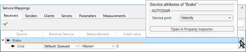
For more information, see Model AUTOSAR Adaptive Service Interfaces with Methods and Events in Simulink.
On the Senders tab, you can set the Sender
Service property. Additionally, in rate-based models you can click on the
pencil icon
at the end of the entry to open the dialog box for configuring the additional
property, Sample time.

Map Tunable Model Elements to Tuning Services
Use the Parameters tab of the Service Mappings editor to map tunable model elements to parameter tuning services. In the table, there are five parent entries that correspond to the five types of tunable model elements, each with collapsible child entries:
Model Parameters Arguments
Model Parameters
Model Variant Control Arguments
Model Variant Controls
Model Variant Variables
For information about model parameters, see Simulink.Parameter,
Simulink.VariantVariable, and Simulink.VariantControl.
For each tunable model element, you can configure the Parameter Tuning
Service property. This property determines whether the generated code
includes elements that allow tuning of the code variable representing the tunable model
element. Select Tunable to include code elements that allow
tuning of the variable, or Not tunable to exclude these code
elements.
In addition, you can click on the
icon at the end of an entry to open the dialog box to configure these additional properties:
Identifier — Identifier of the variable in the generated code.
Calibration Access — Calibration type for the parameter in the ASAP2 file, specified as
CalibrationorNoCalibration. SelectCalibrationto allow the calibration of the corresponding variable in the calibration tool. SelectNoCalibrationto block the option of calibrating it in the tool.Display Identifier — Optional property for the name of the corresponding variable in calibration tool, as indicated in the ASAP2 file.
Format — Format to use for displaying the corresponding variable in calibration tool, as indicated in the ASAP2 file, specified as
%, wherelength.layoutlengthandlayoutare integers. Leave the Format property empty to have the calibration tool use the format of the CompuMethod with the corresponding variable.CompuMethod — Conversion method name in the ASAP2 file, specified as a text scalar. The method is used for converting the ECU-internal value to a physical value for easy readability. Leave the CompuMethod property empty to have the calibration tool use the default method with the corresponding variable.

See Also
Service Mappings Editor | In Bus Element | Out Bus Element

