Explore Link-Level Simulation of Bluetooth Low Energy HDT PHY Waveforms
This example shows how to perform a link-level simulation of Bluetooth® low energy (LE) High Data Throughput (HDT) physical layer (PHY) waveforms to improve wireless audio resilience in congested environments, in accordance with the HDT draft specifications [2]. In congested environments such as malls or airports, users often experience brief audio dropouts caused by interference from other wireless devices. LE HDT enables higher-rate transmissions, and supports sending essential audio or metadata information in compact, rapid bursts. This example shows how to model this behavior at the link level in a broadcast audio scenario.
Using this example, you can:
Create, configure, and generate Bluetooth LE HDT metadata bursts in HDT PHY modes such as HDT2, HDT3, HDT4, HDT6, and HDT7.5.
Integrate the Bluetooth LE channel selection hopping algorithm so that each short HDT burst transmits on a different BLE data-channel index, as determined by the specified channel selection algorithm, CSA #1 or CSA #2.
Apply additive white Gaussian noise (AWGN) channel conditions to approximate the noise-limited environment experienced by wireless audio devices.
Receive and decode high-speed metadata bursts using matched filtering, demodulation, dewhitening, and forward-error-correction (FEC) decoding.
Evaluate bit error rate (BER) and packet error rate (PER) against Eb/No to determine the signal-to-noise ratio (SNR) required for reliable metadata delivery when using faster HDT transmissions.
Visualize and compare BER results across multiple HDT modes to analyze how different throughput levels affect robustness of the waveforms.
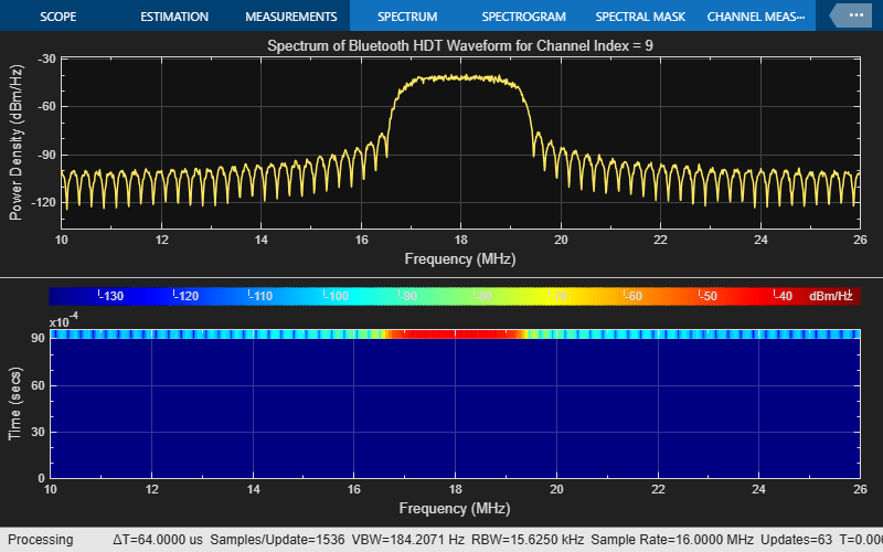
Visualize the spectrum and spectrogram of the HDT waveform and analyze its frequency-domain behavior and frequency-domain behavior over time, respectively.
You can further explore this example to compare and plot BERs and data rates for different HDT PHY modes. For more information, see Further Exploration.
Bluetooth LE HDT PHY
The Bluetooth LE HDT PHY supports coded data rates of 2 Mb/s (HDT2), 3 Mb/s (HDT3), 4 Mb/s (HDT4), 6 Mb/s (HDT6), and 7.5 Mb/s (HDT7.5), with a fixed symbol rate of 2 Msym/s. This table shows how the LE HDT PHY achieves these five HDT data rates by combining three coherent modulation schemes with convolutional coding and puncturing.
LE HDT PHY Mode | Effective Bit Rate | Modulation Scheme | Coding Rate | Puncturing Pattern |
HDT2 | 2 Mb/s | π/4 QPSK | 1/2 | [1 1] |
HDT3 | 3 Mb/s | π/4 QPSK | 3/4 | [1 1 0 1 0 1] |
HDT4 | 4 Mb/s | 8 PSK | 2/3 | [1 1 0 1] |
HDT6 | 6 Mb/s | 16 QAM | 3/4 | [1 1 0 1 0 1] |
HDT7.5 | 7.5Mb/s | 16 QAM | 15/16 | [1 1 0 1 1 0 1 0 1 0 0 1 0 1 0 1 1 0 1 0 0 1 0 1 0 1 1 0 0 1] |
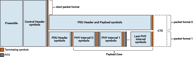
Bluetooth LE HDT specifies three packet format variants.
Short format
Packet format 0
Packet format 1
The Control Header indicates the format in use. Packets that use the short format do not include a protocol data unit (PDU) Header Zone, Payload Zone, or constant tone extension (CTE). Packets that use packet format 0 or packet format 1 include a PDU Header Zone and may include a Payload Zone, a CTE, or both.
This figure shows the structure of HDT packet formats.
This example enables you to generate and receive Bluetooth LE HDT waveforms with packet format 0 and packet format 1.
Example Procedure
This figure shows the example procedure.
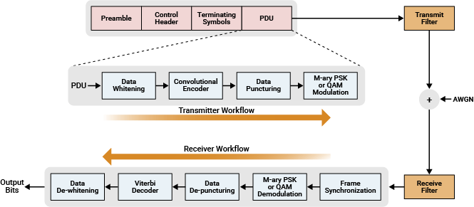
To generate and receive Bluetooth LE HDT waveforms, the example performs these steps. The generated HDT waveform mimics the HDT bursts containing the metadata transmissions that the earbuds need to frequently receive.
Generate the preamble, control header and terminating symbols.
Whiten the PDU data.
Perform punctured convolutional encoding for the selected HDT PHY mode.
Modulate the data symbols by using quadrature amplitude modulation (QAM) or phase shift keying (PSK) for the chosen HDT PHY mode.
Concatenate the preamble, control header, terminating symbols and PDU fields to form a PHY frame.
Upsample and filter the PHY frame through a transmit filter.
Pass the generated waveform through an AWGN channel.
Filter and downsample the received noisy waveform for matched filtering.
Perform preamble detection for frame synchronization.
Demodulate and decode the control header.
Demodulate the data symbols by using QAM or PSK for the selected HDT PHY mode.
Depuncture and Viterbi decode the demodulated data symbols by using an unquantized method.
Dewhiten the data to retrieve the output bits.
Compare the output bits with the PDU bits to evaluate BER and PER performance.
Simulation Configuration
Specify the HDT PHY mode. Set the samples per symbol, number of bits to simulate, Eb/No, and HDT packet format values.
hdtMode ="HDT6"; % HDT PHY mode packetFormat =
"format0"; % HDT packet format sps = 8; % Samples per symbol dataLength =
511; % Data length in octets EbNo = -2:2:14; % Information bit Eb/No in dB
For packet format 1, specify the length of each payload block.
if strcmp(packetFormat,"format1") payloadBlockLength =128; % Length of each payload block in symbols for format1 else % For short and format0 payloadBlockLength = []; end
Bluetooth LE Channel Selection
Enable frequency hopping. Specify the channel selection algorithm as 1 for algorithm #1 and 2 for algorithm #2.
frequencyHopping =1; csa =
1;
Create and configure a bleChannelSelection System object™ , specifying the type of channel selection algorithm and used channels.
if frequencyHopping
    frequencyHop = bleChannelSelection(Algorithm=csa);
    frequencyHop.UsedChannels = [0 5 9 13 24];
    if(csa == 1)
        frequencyHop.HopIncrement = 8;
    end
end
To ensure repeatability of results, set the seed for the random number generator to 0. The seed value controls the pattern of random number generation, so initializing the random number generator using the same seed ensures the same result. To improve the accuracy of your results, after running the simulation, you can change the seed value, run the simulation again, and average the results over multiple simulations.
rng(0)
Initialize the Bluetooth LE HDT parameters for transmitter and receiver.
[hdtParams,fecParams,filterParams] = helperBLEHDTInit(hdtMode,packetFormat,payloadBlockLength,sps);
Specify the symbol rate (in symbols/second) and channel bandwidth (in Hz) for the HDT PHY mode.
symbolRate = 2e6;
channelBW = 2e6;
Specify the FEC code rate and modulation order. Compute the numerator and denominator of the FEC code rate.
codeRate = hdtParams.codeRate;    % FEC code rate
M = hdtParams.M;                  % Modulation order
Compute bits per symbol from the specified modulation order.
k = log2(M);
Compute the data rate (in bits/second) of the HDT PHY waveform.
dataRate = symbolRate*k*codeRate; % In bits/secondConvert the Eb/No value to the SNR.
snr = convertSNR(EbNo,"ebno",BitsPerSymbol=k,CodingRate=codeRate,SamplesPerSymbol=sps);Create and configure comm.ErrorRate System object to compute the symbol error rate of the input HDT PHY waveform.
error = comm.ErrorRate();
Pre-allocate space to store the BER and PER results.
ber = zeros(1,length(snr));
per = zeros(1,length(snr));
Specify small values for maxNumErrors and maxNumPackets in this example. maxNumErrors defines the maximum number of bit errors simulated at each Eb/No point. When the number of bit errors reaches this limit, the simulation at that Eb/No point completes. maxNumPackets defines the maximum number of packets simulated at each Eb/No point and limits the simulation length if the bit error limit is not reached. To obtain statistically meaningful results, you can run the simulation again with larger values for maxNumErrors and maxNumPackets.
maxNumErrors = 1000;
maxNumPackets = 100;
Visualization
Create and configure a timescope and a spectrum analyzer to visualize the time-domain signal and the frequency spectrum of the time-domain signal, respectively.
timeScopeVis = timescope(SampleRate=symbolRate*sps,TimeSpanSource="Auto", ...
    ShowLegend=true);
specAnalyzer = spectrumAnalyzer(Method="welch", ...
    SpectrumType="Power density", ...
    ViewType="spectrum-and-spectrogram", ...
    SampleRate=symbolRate*sps);
Display the data rate and code rate of the simulated Bluetooth LE HDT link.
disp("Simulating Bluetooth HDT link for packet " + packetFormat + " with " + hdtMode + " PHY mode " + "at a data rate " + num2str(dataRate/1e6) + " Mbps.")
Simulating Bluetooth HDT link for packet format0 with HDT6 PHY mode at a data rate 6 Mbps.
Simulation
Simulate HDT bursts reliably across each Eb/No point.
for countSNR = 1:length(snr)
    numErrors = 0;
    numPackets = 0;
    numPacketErrors = 0;
For each Eb/No point, perform these steps to generate and process the packets.
Generate random bits.
Select a channel index.
Generate a Bluetooth HDT waveform.
Add AWGN to the generated waveform.
Decode the data bits by feeding the noisy waveform to an HDT receiver.
Calculate the BER and PER.
    while numErrors<maxNumErrors && numPackets<maxNumPackets
        txData = randi([0 1],dataLength*8,1);
When frequency hopping is on, allocate the channel index based on the specified channel selection algorithm. If you turn off frequency hopping, the Central device selects a random channel index in the range [0, 39].
        if frequencyHopping
            channelIndex = frequencyHop();       % Channel index based on frequency hopping
        else
            channelIndex = mod(numPackets-1,40); % Channel index without frequency hopping
        end

        % Combined transmitter processing
        txWaveform = helperBLEHDTWaveform(txData,channelIndex,hdtParams,fecParams,filterParams);

        [rxSig,nVar] = awgn(txWaveform,snr(countSNR),"measured");

        % Combined receiver processing
        dewhitenedData = helperBLEHDTReceiver(rxSig,channelIndex,hdtParams,fecParams,filterParams,nVar);

        % BER and PER calculation
        errors = error(txData,dewhitenedData(1:length(txData)));
        ber(countSNR) = errors(1);
        numErrors = errors(2);
        bitErrorsThisPacket = sum(txData ~= dewhitenedData(1:length(txData)));
        if bitErrorsThisPacket > 0
            numPacketErrors = numPacketErrors + 1;
        end
        numPackets = numPackets + 1;
    end
    per(countSNR) = numPacketErrors/numPackets;
Visualization and Results
Visualize and plot the BER and time-frequency behavior of the Bluetooth LE HDT burst waveform.
specAnalyzer.FrequencyOffset = channelBW*channelIndex;
specAnalyzer.Title = "Spectrum of Bluetooth HDT Waveform for Channel Index = " + num2str(channelIndex);
specAnalyzer(txWaveform)
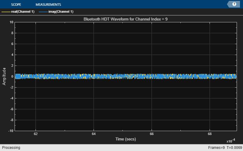
timeScopeVis.Title = "Bluetooth HDT Waveform for Channel Index = " + num2str(channelIndex);
timeScopeVis(txWaveform)Display the BER values for each Eb/No point.
    disp("Simulating for Eb/No = " + num2str(EbNo(countSNR)) + " dB, BER: " + num2str(ber(countSNR)) + " PER: " + num2str(per(countSNR)))
    reset(error)
end
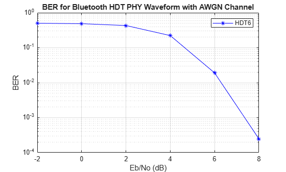
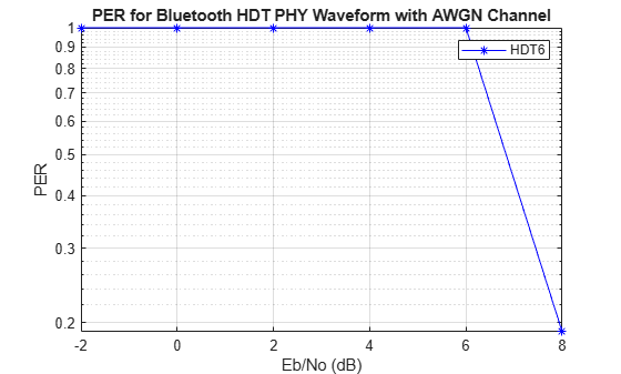
Simulating for Eb/No = -2 dB, BER: 0.50147 PER: 1
Simulating for Eb/No = 0 dB, BER: 0.48704 PER: 1
Simulating for Eb/No = 2 dB, BER: 0.43151 PER: 1
Simulating for Eb/No = 4 dB, BER: 0.2226 PER: 1
Simulating for Eb/No = 6 dB, BER: 0.019045 PER: 1
Simulating for Eb/No = 8 dB, BER: 0.00024706 PER: 0.19
Simulating for Eb/No = 10 dB, BER: 0 PER: 0
Simulating for Eb/No = 12 dB, BER: 0 PER: 0
Simulating for Eb/No = 14 dB, BER: 0 PER: 0
For the specified HDT PHY mode, plot the BER results for each input Eb/No range. The plot illustrates the SNR levels required for HDT bursts to prevent audio dropouts in congested environments. At low Eb/No values, noise significantly affects many bursts. As Eb/No rises above 2 dB, the bit error rate drops sharply, and by 10 dB, the receiver can almost perfectly recover each burst. Higher Eb/No values enable the bursts to slip through interference with minimal errors.
semilogy(EbNo,ber,"b-*")
grid on
legend(hdtMode)
xlabel("Eb/No (dB)")
ylabel("BER")
title("BER for Bluetooth HDT PHY Waveform with AWGN Channel")
semilogy(EbNo,per,"b-*")
grid on
legend(hdtMode)
xlabel("Eb/No (dB)")
ylabel("PER")
title("PER for Bluetooth HDT PHY Waveform with AWGN Channel")
Further Exploration
You can use this example to further explore these capabilities.
Compare BER for Different HDT PHY Modes
Using this example, you can compare the bit error rate performance of different HDT PHY modes. To achieve this:
Simulate the BER plot for each of the HDT PHY modes individually.
Copy the plots for all HDT PHY modes into a single figure that shows the BER comparison for various HDT PHY modes.
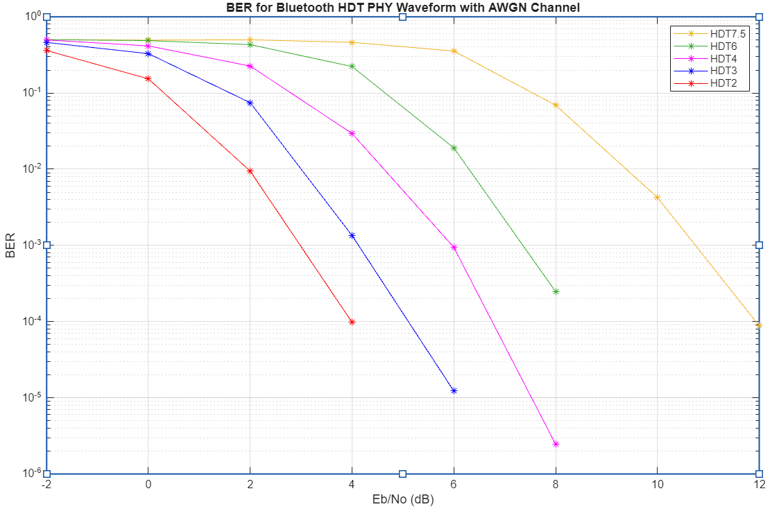
As Eb/No increases, the BER decreases for all waveforms, indicating improved reliability at higher signal-to-noise ratios. Among the waveforms, HDT2 achieves the lowest BER at lower Eb/No values, while HDT7.5 requires a much higher Eb/No to reach similar BER performance, showing that higher-order waveforms are more susceptible to noise. This demonstrates the tradeoff between data rate and robustness to noise in Bluetooth PHY waveforms.
Compare Data Rates for Different HDT PHY Modes
To compare data rates for different HDT PHY modes, uncomment this code and simulate the example.
% hdtMode = {"HDT2","HDT3","HDT4","HDT6","HDT7.5"};
% sps = 8;
% packetFormat = "format0";
% if strcmp(packetFormat,"format1")
%     payloadBlockLength = 128;
% else
%     payloadBlockLength = [];
% end
% symbolRate = 2e6;
% dataRate = zeros(length(hdtMode),1);
% for idx = 1:length(hdtMode)
%     mode = char(hdtMode(i));
%     hdtParams = helperBLEHDTInit(hdtMode,packetFormat,payloadBlockLength,sps);;
%     codeRate = hdtParams.codeRate;
%     M = hdtParams.M;
%     k = log2(M);
%     dataRate(idx) = symbolRate*k*codeRate;
% end
% bar(dataRate)
% xlabel("HDT PHY Mode")
% ylabel("Data rate (b/sec)")
% title("Data Rate of Different PHY Modes of Bluetooth HDT Waveform")
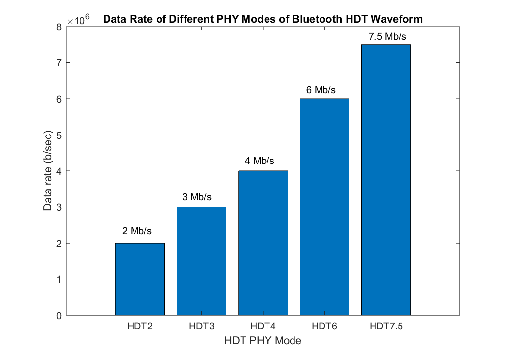
As the HDT PHY mode increases from HDT2 to HDT7.5, the data rate rises from 2 Mb/s to 7.5 Mb/s. Each successive PHY mode increases throughput by transmitting more information bits per symbol and reducing overhead while keeping the symbol rate fixed. HDT2 uses the smaller modulation order and coding rate, resulting in the lowest data rate but offering the highest robustness for challenging channels. In contrast, HDT7.5 uses the higher modulation order and coding rate, delivering maximum data rate and spectral efficiency, but requiring better channel conditions for reliable communication.
Appendix
The example uses these helper functions, attached as supporting files:
helperBLEHDTInit— Initialize Bluetooth LE HDT transmitter and receiver parameters.helperBLEHDTPreamble— Generate Bluetooth LE HDT PHY preamble.helperBLEHDTReceiver— Demodulate and decode the Bluetooth LE HDT waveform.helperBLEHDTWaveform— Generate Bluetooth LE HDT waveform.helperBLEHDTWhiten— Perform Bluetooth LE HDT data whitening and dewhitening.
References
[1] Bluetooth Technology Website. "Bluetooth Technology Website | The Official Website of Bluetooth Technology."Accessed Jan 05, 2026. https://www.bluetooth.com/.
[2] LE High Data Throughput (HDT) - Physical Layer | "Bluetooth Technology Website." Accessed Nov 26, 2025. https://www.bluetooth.com/specifications/specs/le-high-data-throughput-physical-layer/.
See Also
Objects
bleChannelSelection|spectrumAnalyzer(DSP System Toolbox) |timescope(DSP System Toolbox)