Test Fault Mitigation Logic by Using Fault Tree Analysis
R2026bThis example shows how to verify fault mitigation logic by using a fault tree. The aircraft elevator system in this example has two elevators, one for each wing. Each elevator has two actuators and an independent hydraulic circuit, and both elevators share an additional hydraulic circuit. To mitigate the effects of faults on the elevator, the model includes fault mitigation logic that detects and contains each fault.
A fault tree is a predictive analysis that expresses the fault combinations that cause a system-level failure. In this example, the fault tree predicts how the mitigation logic responds to each fault and links each basic event to a Simulink Fault Analyzer fault in the model. You then simulate the linked faults directly from the fault tree and compare the results against its predictions. Where the model behaves differently than the fault tree predicts, the fault tree flags the discrepancy for you to resolve.
Open and Set Up the Example Files
Open the example model and fault tree, and set up the faults and links by using the aircraftFaultTreeSetup helper function. The helper function deletes the existing Simulink Fault Analyzer model artifacts, replaces them with the faults used in the example, and establishes the links between the fault tree document and the model.
mdlName = "aircraftElevatorFaultAnalyzer";
open_system(mdlName)
ftaName = "elevatorFaultTree.mldatx";
aircraftFTA = safetyAnalysisMgr.openDocument(ftaName);
aircraftFaultTreeSetup
Inspect the Fault Tree Document
Open the Safety Analysis Manager to view the fault tree document, elevatorFaultTree.mldatx.
safetyAnalysisManager
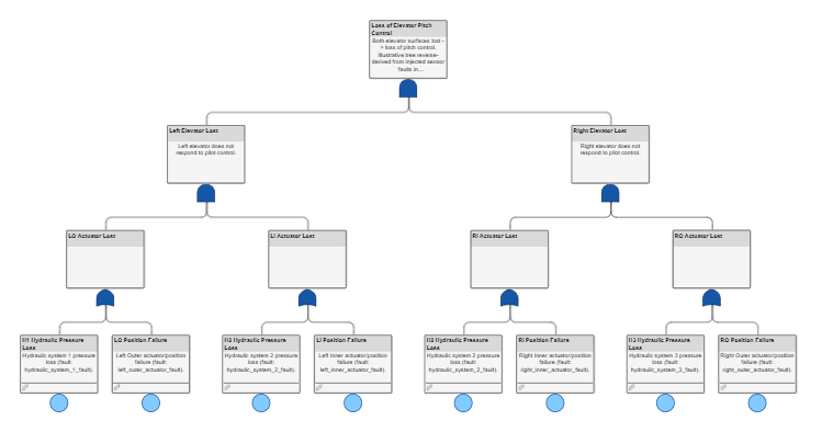
The fault tree document predicts how faults combine to cause a loss of the elevator. In the fault tree:
The top-level gate represents the total loss of control of the aircraft elevator. Both the left and the right elevators must fail in order for the failure to occur.
The
Left Elevator LostandRight Elevator Lostgates represent the loss of the left or right elevator. An elevator fails only if the interior and exterior elevators on that side fail.Seven basic events contribute to the failure at the top-level gate. In this example, these events are linked to faults in the model. Three of the faults affect the hydraulic systems, and four affect the actuator positions.
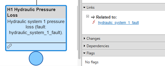
To link each basic event to its corresponding fault in the model, the fault tree document uses Requirements Toolbox™ links. Point to the link icon to view the links. You can also view the links by selecting the event. In the Properties pane, expand the Links section.
Inspect the Model and Faults
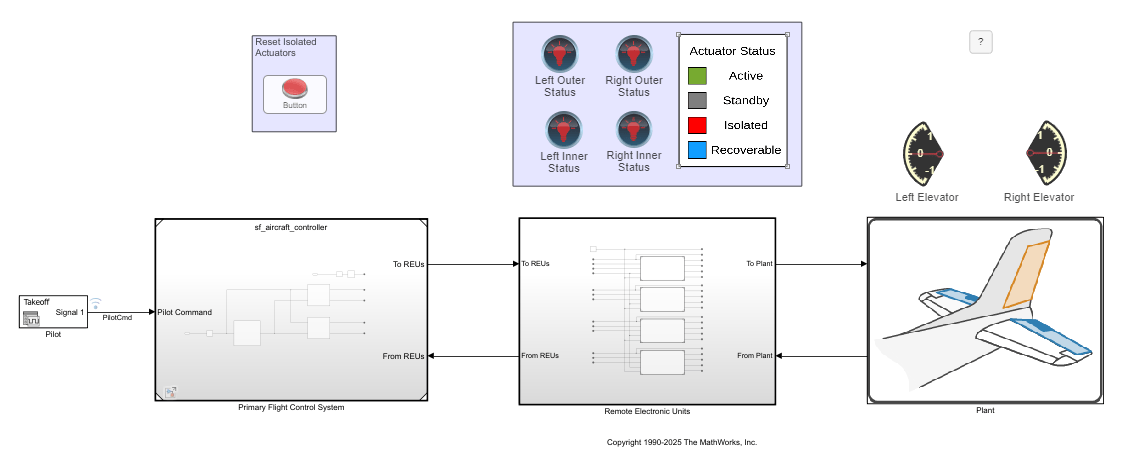
View the aircraftElevatorFaultAnalyzer.slx model. This model replaces the faults in the model in the Detect and Isolate Faults in an Aircraft Elevator Control System (Stateflow) example with Simulink Fault Analyzer faults. The model contains seven faults, each of which corresponds to a basic event in the fault tree.
Open the Fault Table pane to view the faults. In the Apps tab, click Fault Analyzer. In the Fault Analyzer tab, in the View section, click Fault Table.
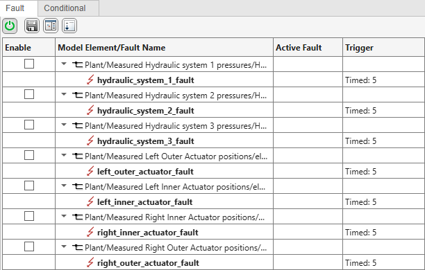
The model has faults at different levels of the model hierarchy. To view the location of a fault, right-click the fault and select Show faulted model element in canvas. The Simulink Editor opens and highlights the location of the fault.
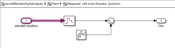
When injected, the fault on each hydraulic system drops the hydraulic pressure to 100, and the fault on each actuator holds the position at 15. To view the behaviors, in the Fault Table pane, right-click the fault and select Open fault behavior.
Simulate and Resolve Design Inconsistencies
To execute code from the fault tree document, you create and execute a callback. See Write Callbacks to Analyze Safety Analysis Manager Spreadsheets. In this example, the fault tree document executes a callback when you click Analyze Document  . The callback runs the code in the custom MATLAB® function
 validateAircraftFTAUsingSimulation. The callback runs a simulation that injects each fault. After running the simulation, the callback checks the simulation data to confirm whether the fault caused a loss in the left or right elevator. If the pilot control deviates from the elevator position beyond a specified threshold, the script flags a failure.
Verify that the fault logic in the fault tree models this behavior. Click Analyze Document  .
.
runAnalysis(aircraftFTA)
After injecting and simulating each fault, the analysis determines that four of the faults individually caused the left elevator to fail. To indicate these results, the fault tree adds error flags to four of the events and to the Left Elevator Lost gate. Point to the flags to see the messages.
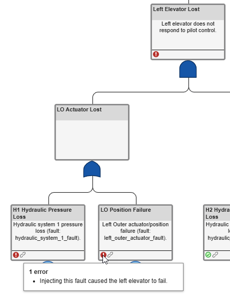
These results indicate that the logic in the fault tree is inconsistent with the model.
Investigate the Inconsistency and Update the Model
Creating parity between your design and the fault tree is iterative. In this example, you update the control logic to solve the discrepancy.
In the model, open the primary flight control unit (PFCU) that models the fault mitigation logic for the inner-left actuator. Open the Primary Flight Control System referenced model, and then open the PFCU2 subsystem. The PFCU2 subsystem models the control systems for the inner-left and inner-right actuators. Open the Left Inner chart to inspect the logic.
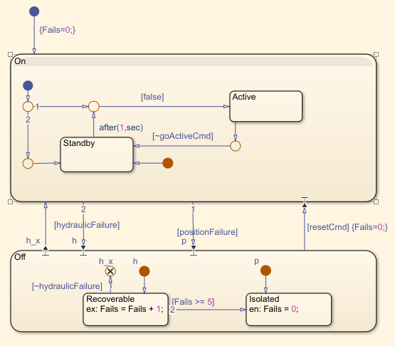
The transition labeled false does not implement the intended logic. When the left actuator is inactive and there are no faults, the elevator tracks the pilot command normally. When the goActiveCmd input is true because of a fault, the chart should enter the Active state. Instead, nothing happens. To fix the transition, double-click the transition and enter goActiveCmd.
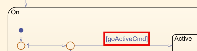
After updating the transition, save the model and run the analysis of the fault tree document again. This time, each event has a check flag. The fault tree document now predicts that each fault individually does not cause a failure to either elevator.
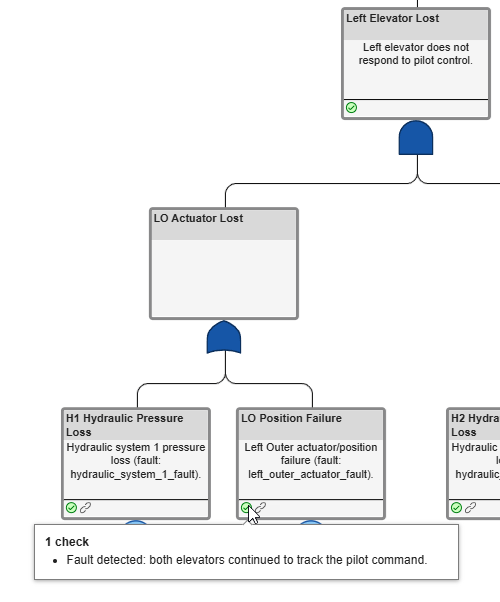
If the fault mitigation logic requires additional protections, such as resilience against more than one fault, update the mitigation logic, then update the fault tree and the callback, and rerun the analysis.

