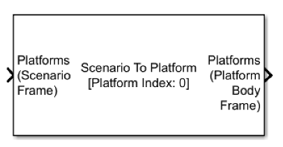
Scenario To Platform
Libraries:
Sensor Fusion and Tracking Toolbox /
Tracking Scenario and Sensor Models
Description
The Scenario To Platform block transforms platform poses expressed in the scenario frame to platform poses expressed in a platform body frame.
Ports
Input
Platform poses expressed in the scenario frame, specified as a Simulink bus containing a MATLAB structure. For more details about buses, see Create Nonvirtual Buses (Simulink). The structure has these fields.
| Field | Description |
|---|---|
NumPlatforms | Number of platforms, specified as a nonnegative integer. |
Platforms | Platform poses in the scenario frame, specified as an array of platform
pose structures. The block reads only as many platform poses as the number
of platforms specified in NumPlatforms. |
The fields of each platform pose structure are:
| Field | Description |
|---|---|
PlatformID | Unique identifier for the platform, specified as a positive integer. |
ClassID | User-defined integer used to classify the type of target,
specified as a nonnegative integer. |
Position | Position of the platform in the scenario frame, specified as a real-valued 1-by-3 vector. Units are in meters. |
Velocity | Velocity of the platform in the scenario frame, specified as a real-valued 1-by-3 vector. Units are in meters per second. |
Acceleration | Acceleration of the platform in the scenario frame, specified as a real-valued 1-by-3 vector. Units are in meters per second-squared. |
Orientation | Orientation of the platform with respect to the scenario frame, specified as a 3-by-3 rotation matrix. Orientation defines the frame rotation from the scenario frame to the platform body frame. |
AngularVelocity | Angular velocity of the platform in the scenario frame, specified as a real-valued 1-by-3 vector. The magnitude of the vector defines the angular speed. Units are in degrees per second. |
Instead of specifying target platform poses directly, you can use the Tracking Scenario Reader block to generate platform poses expressed in the scenario frame.
Reference platform pose expressed in the scenario frame, specified as a Simulink bus containing a MATLAB structure. For more details about buses, see Create Nonvirtual Buses (Simulink). The structure has these fields:
| Field | Description |
|---|---|
PlatformID | Unique identifier for the platform, specified as a positive
integer. The specified |
ClassID | User-defined integer used to classify the type of target,
specified as a nonnegative integer. |
Position | Position of the platform in the scenario frame, specified as a real-valued, 1-by-3 vector. Units are in meters. This is a required field with no default value. |
Velocity | Velocity of the platform in the scenario frame, specified as a real-valued, 1-by-3 vector. Units are in meters per second. This is a required field with no default value. |
Acceleration | Acceleration of the platform in the scenario frame, specified as a 1-by-3 vector. Units are in meters per second-squared. This is a required field with no default value. |
Orientation | Orientation of the platform with respect to the scenario frame, specified as a 3-by-3 rotation matrix. Orientation defines the frame rotation from the scenario frame to the platform body frame. This is a required field with no default value. |
AngularVelocity | Angular velocity of the platform in the scenario frame, specified as a real-valued, 1-by-3 vector. The magnitude of the vector defines the angular speed. Units are in degrees per second. This is a required field with no default value. |
Dependencies
To enable this port, select the Enable reference platform pose input check box.
Output
Target platform poses expressed in the body frame of the reference platform,
specified as a Simulink bus containing a MATLAB structure. For more details about buses, see
Create Nonvirtual Buses (Simulink). The reference platform is the platform whose
PlatformID is specified in the Reference platform
index parameter. The structure has these fields.
| Field | Description |
|---|---|
NumPlatforms | Number of platforms, specified as a nonnegative integer. |
Platforms | Platform poses, specified as an array of platform pose structures. The
block reads only as many platform poses as the number of platforms specified
in NumPlatforms. |
Each platform pose structure contains these fields.
| Field | Description |
|---|---|
PlatformID | Unique identifier for the target platform, returned as a positive integer. |
ClassID | User-defined integer used to classify the type of target
platform, returned as a nonnegative integer. |
Position | Position of the target platform in the reference platform body frame, returned as a real-valued 1-by-3 vector. Units are in meters. |
Velocity | Velocity of the target platform in the reference platform body
frame, returned as a real-valued 1-by-3 vector. Units are in meters per
second. The default is |
Acceleration | Acceleration of the target platform in the reference platform
body frame, returned as a real-valued 1-by-3 vector. Units are in meters
per second-squared. The default is |
Orientation | Orientation of the target platform with respect to reference platform body frame, returned as a 3-by-3 rotation matrix. Orientation defines the frame rotation from the reference platform body frame to the target platform body frame. |
AngularVelocity | Angular velocity of the target platform in the reference platform body frame, specified as a real-valued 1-by-3 vector. The magnitude of the vector defines the angular speed. Units are in degrees per second. |
You can use this output as the input to the Fusion Radar Sensor block.
Parameters
Reference platform index, specified as a positive integer. You must specify the platform pose corresponding to this index through the Platforms (Scenario Frame) input port, or through the Reference Platform Pose (Scenario Frame) input port.
Example: 1
Select this checkbox to enable the Reference Platform Pose (Scenario Frame) input port.
Source of the output bus name, specified as one of these options:
Auto— The block automatically creates a bus name.Property— Specify the bus name by using the Specify an output bus name parameter.
Output port bus name, specified as a valid bus name.
Dependencies
To enable this parameter, set the Source of output bus name
parameter to Property.
Select the type of simulation to run as:
Interpreted execution— Simulate the model using the MATLAB interpreter. This option shortens startup time. InInterpreted executionmode, you can debug the source code of the block.Code generation— Simulate the model using generated C code. The first time you run a simulation, Simulink generates C code for the block. The C code is reused for subsequent simulations as long as the model does not change. This option requires additional startup time.
Extended Capabilities
C/C++ Code Generation
Generate C and C++ code using Simulink® Coder™.
Version History
Introduced in R2022bAs of R2023a, the Simulink buses created by this block no longer show in MATLAB workspace.
See Also
Tracking Scenario Reader | Fusion Radar Sensor | Create Nonvirtual Buses (Simulink)
MATLAB Command
You clicked a link that corresponds to this MATLAB command:
Run the command by entering it in the MATLAB Command Window. Web browsers do not support MATLAB commands.
Seleccione un país/idioma
Seleccione un país/idioma para obtener contenido traducido, si está disponible, y ver eventos y ofertas de productos y servicios locales. Según su ubicación geográfica, recomendamos que seleccione: .
También puede seleccionar uno de estos países/idiomas:
Cómo obtener el mejor rendimiento
Seleccione China (en idioma chino o inglés) para obtener el mejor rendimiento. Los sitios web de otros países no están optimizados para ser accedidos desde su ubicación geográfica.
América
- América Latina (Español)
- Canada (English)
- United States (English)
Europa
- Belgium (English)
- Denmark (English)
- Deutschland (Deutsch)
- España (Español)
- Finland (English)
- France (Français)
- Ireland (English)
- Italia (Italiano)
- Luxembourg (English)
- Netherlands (English)
- Norway (English)
- Österreich (Deutsch)
- Portugal (English)
- Sweden (English)
- Switzerland
- United Kingdom (English)