Workflow Advisor
Generate synthesizable HDL code and test benches from MATLAB code
Description
Use the Workflow Advisor app to convert MATLAB functions into synthesizable HDL code. You can then implement the generated code on FPGAs or ASICs.
Use the app to prepare, validate, and generate HDL (VHDL®, Verilog®, or SystemVerilog) code. Use the MATLAB HLS Workflow Advisor to prepare, validate, and generate HLS (SystemC™/SynthesizableC++) code. For more information on the MATLAB HLS Workflow Advisor, see Workflow Advisor.
You can:
Check MATLAB code for HDL compatibility and readiness.
Perform automated fixed-point conversion.
Generate synthesizable HDL code and corresponding test benches.
Customize the target and synthesis tool settings.
Integrate with third-party FPGA tools.
Package and deploy your design to supported hardware platforms.
Note
Workflow Advisor is not available in MATLAB® Online™.
Open the Workflow Advisor
In the MATLAB Toolstrip, on the Apps tab, select HDL Coder.
In the HDL Code Generation window, add the MATLAB function file and the MATLAB test bench in the MATLAB Function and MATLAB Test Bench sections, respectively.
Define the input types. You can manually enter the input types or use a test bench to automatically define them. To use a test bench:
Click the Autodefine types link.
In the Autodefine Input Types dialog box, click the Add a file button
 to add a test bench file or, select one from the list.
Click Run.
Click the Workflow Advisor button.
Note
Sometimes HDL Coder cannot determine whether the entry-point functions in your project are suitable for HDL code generation. The most likely reason is that HDL Coder is unable to find the entry-point files. Verify that your current working folder is set to the folder that contains your entry-point files. If it is not, either make this folder your current working folder or add the folder containing these files to the MATLAB path.
Examples
Parameters
HDL Workflow Advisor
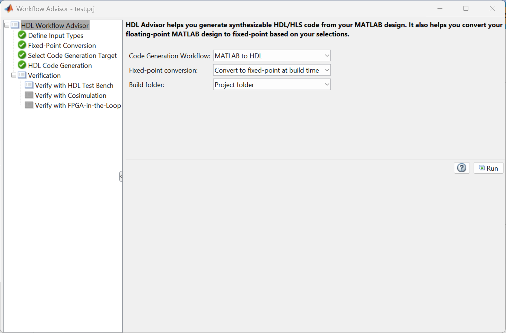
Specify the type of code to generate from your MATLAB code:
MATLAB to HDL— Generate HDL code in VHDL or Verilog.MATLAB to HLS— Generate HLS code inSystemCorSynthesizableC++.
Specify whether to convert the floating-point data in your design:
Convert to fixed-point at build
                                                  time
— Use the Fixed-Point Conversion tool to convert floating-point types to fixed-point during code generation.Keep original types— Retain the data types in the original MATLAB algorithm.
Choose where to store generated build files:
Project folder— Store build files in the project folder.Specified folder— Choose a custom location.
Enter a folder name in which to store the build files, or click Browse to select an existing folder.
Dependencies
To enable this parameter, set Build folder to Specified folder.
Define Input Types
This parameter is read-only. This parameter displays the MATLAB function that you generate code from.
Specify the test script or function that calls the MATLAB function for validation.
Use the Add a file button ![]() to add a new test bench and the Remove selected file
button
to add a new test bench and the Remove selected file
button ![]() to remove the selected test bench.
to remove the selected test bench.
Select this parameter to enable frame-to-sample conversion. The frame-to-sample conversion reduces the FPGA I/O needed to handle a large input signal by converting the matrix inputs to smaller samples and streaming the input signal.
Fixed-Point Conversion
Use the Fixed-Point Conversion tool to convert the floating-point data types in your DUT to fixed-point. For more information on how to use the Fixed-Point Conversion tool, see Automated Fixed-Point Conversion.
Dependencies
To enable this task, set Fixed-Point Conversion to
Convert to fixed-point at build time.
Select Code Generation Target
Select the HDL code generation workflow to apply to the MATLAB function:
Generic ASIC/FPGA— Generate generic HDL code or a programming file for a specific FPGA.IP Core Generation— Generate a custom IP core and integrate it with embedded software in an embedded system integration project.
Choose the hardware platform for which to generate the custom IP core. The options differ based on the products and support packages you have installed.
To install additional hardware platforms, launch the Add-On Explorer by selecting
Get more.
Dependencies
To enable this parameter, set Workflow to
IP Core Generation.
Choose the synthesis tool that matches your target hardware and development
environment. You do not need to specify a synthesis tool if you want to generate generic
HDL code. When you set Workflow to IP Core
Generation, the setting of Platform determines the
options that appear in this parameter.
No synthesis tool specified— Use this setting when you do not need to target a specific hardware device.Altera QUARTUS II— Target Altera® hardware.Cadence Genus— Target supported hardware using the Cadence® Genus synthesis tool.Intel Quartus Pro— Target Intel® hardware.Microchip Libero SoC— Target Microchip hardware using Libero® SoC.Xilinx ISE— Target Xilinx® hardware using the ISE tool.Xilinx Vivado— Target Xilinx hardware using the Vivado® tool.
If no synthesis tool appears in the list, ensure the tool is installed and its path is set up correctly, then click Refresh list.
Choose your target device chip family to use for the synthesis tool. The options for this parameter depend on the setting of the Synthesis tool parameter.
Dependencies
To enable this parameter, set Synthesis tool to a
setting other than No synthesis tool specified.
Choose the device to target for synthesis. This specification determines the specific hardware configuration that the synthesis tool uses during synthesis and implementation.
Dependencies
To enable this parameter, set Synthesis tool to a
setting other than No synthesis tool specified.
Choose the target device package to use for synthesis. This specification determines the physical form factor and pin configuration that the synthesis tool uses during synthesis and implementation.
Dependencies
To enable this parameter, set Synthesis tool, Chip family, and Device to a synthesis tool, chip family, and device that supports different physical package types for synthesis.
Choose the speed grade of the target device to use for synthesis. This specification determines the timing characteristics that the synthesis tool uses during synthesis and implementation.
Dependencies
To enable this parameter, set Synthesis tool, Chip family, and Device to a synthesis tool, chip family, and device that supports different speed grades for synthesis.
Specify the target clock frequency, in MHz, for the generated HDL design. Use this value to configure the clock module and timing constraints during synthesis and implementation.
Select the predefined embedded system integration project into which HDL Coder™ inserts your generated IP core. The reference design defines the hardware and software environment for integrating and testing the IP core.
To create a reference design, see Register a Custom Reference Design.
Dependencies
To enable this parameter, set Workflow to IP Core Generation.
Enter the path to the downloaded reference design components.
Dependencies
To enable this parameter, set Workflow to
IP Core Generation and Reference
design to an embedded system integration project that requires
downloadable components.
Specify the Verilog or VHDL source files to include in your design when using an
hdl.BlackBox
System object™. Enter each file name manually, separated by a semicolon
(;), or use the file selection button ![]() to select a file in the current folder. The source file
language must match your target language.
to select a file in the current folder. The source file
language must match your target language.
Dependencies
To enable this parameter, set Workflow to
IP Core Generation.
Enter a name for the generated IP core. The app uses this field to name the IP core in the
generated files. For example, if you enter myFilter, the tool
generates an IP core named myFilter_ip.
If this field is empty, the tool uses the name of the top-level MATLAB function as the base name for the IP core.
Dependencies
To enable this parameter, set Workflow to IP Core Generation.
Enter a version number or label for the generated IP core. The tool includes this value in the IP core metadata. Use this value to track changes across iterations.
Dependencies
To enable this parameter, set Workflow to IP Core Generation.
Select how the processor and FPGA operate relative to each other during execution:
Free running— The processor and FPGA run independently without automatic synchronization.Coprocessing-blocking— HDL Coder generates synchronization logic so the processor waits for the FPGA to complete execution before continuing. Use this option when the FPGA execution time is short relative to the processor sample time.
Dependencies
To enable this parameter, set Workflow to IP Core Generation.
Note
To enable the Set Target Interface task, in Select Code
Generation Target, set Workflow to IP Core
Generation.
Select Code Generation Target > Set Target Interface
Select the Set Target Interface task to see the fixed-point representation of the MATLAB design. The app generates this code using Fixed-Point Designer™.
The Ports table displays the properties of the input and output functions. Use this table to map these functions to I/O resources on the target device. The table contains these sections:
Inport — Lists input functions to the design
Outport — Lists output functions from the design
These sections display the function names and their data types. Use the Target Platform Interfaces and Bit Range / Address / FPGA Pin columns to map each function to a hardware interface and physical or logical resource on the target platform.
| Column Name | Description |
|---|---|
| Port Name | The name of the function in the MATLAB design. This field is read-only. |
| Data Type | The data type assigned to the function. This field is read-only. |
| Target Platform Interfaces | Specify the interface type on the target hardware platform. For example:
The available options depend on the setting of Device. |
| Bit Range / Address / FPGA Pin | Specify the connection details for the selected interface type:
|
Dependencies
To enable this parameter, set Workflow to
IP Core Generation.
The Build Log tab displays the detailed messages and status updates generated during the code generation process.
Dependencies
To enable this parameter, set Workflow to IP Core Generation.
HDL Code Generation > Target
Specify the HDL language for the generated code:
VHDLVerilogSystemVerilog
Select this parameter to analyze your MATLAB design for compatibility with HDL code generation.
Select this parameter to generate synthesizable HDL code from your MATLAB design.
Select this parameter to generate simulation and synthesis scripts for supported third-party EDA tools.
Select this parameter to generate an HTML report that provides traceability information and details about the generated HDL code.
Select this parameter to generate a report that summarizes the optimizations applied during HDL code generation.
Dependencies
To enable this parameter, enable Generate report.
Select this parameter to generate a report that estimates the hardware resources required for the generated HDL code, such as adders, multipliers, and registers.
HDL Code Generation > Coding Style
Select this parameter to preserve comments from the original MATLAB code in the generated HDL code.
Select this parameter to include the original MATLAB source code as comments in the generated HDL code.
Specify the file extension to use for generated VHDL files.
Specify the file extension to use for the generated Verilog files.
Specify how to initialize registers without reset signals in the generated HDL code:
None— No initialization is performed for registers without reset logic.Script— Generate a separate initialization script for no-reset registers.InsideModule— Insert initialization logic directly inside the HDL module.
Select this parameter to include the current time and date in the header comments of each generated HDL file. Use this parameter to track when the code was generated for versioning or audit purposes.
Specify a comment to insert at the top of each generated HDL and test bench file. Use this parameter to include author information, project details, or version notes.
Specify a prefix to prepend to the name of the generated DUT module in Verilog or SystemVerilog code, or to entity in VHDL code. Use this parameter to customize the naming schema or to match project or organizational conventions.
Specify a postfix to append to the model or subsystem name to form the name of a package file. Use this parameter to distinguish package files when generating HDL code for multiple designs and configurations.
Specify a postfix to append to the DUT name to form the name of the generated timing controller file. Use this parameter to uniquely identify timing controller components when generating HDL code for multiple designs or configurations.
Specify a postfix to append to duplicate VHDL entity or Verilog and SystemVerilog module names. If name conflicts occur during code generation, HDL Coder resolves them by appending this postfix to ensure unique identifiers.
Specify a postfix to append to names of entities, signals, constants, or other MATLAB code elements that conflict with reserved words in the target HDL. If name conflicts occur during code generation, HDL Coder resolves them by appending this postfix to ensure unique identifiers.
Specify a postfix to append to the names of generated HDL clocked processes. Use this parameter to distinguish clocked processes in the generated code, especially when multiple processes are present or naming conflicts may occur.
Specify a postfix to append to the names of the real part of complex signals in the generated HDL code. Use this parameter to distinguish real and imaginary components when complex data types are split during code generation.
Specify a postfix to append to the names of the imaginary part of complex signals in the generated HDL code. Use this parameter to distinguish real and imaginary components when complex data types are split during code generation.
Specify a postfix to append to the names of generated pipeline registers in the HDL code. Use this parameter to identify and distinguish pipeline stages added during code generation.
Specify a prefix to prepend to the names of enable signals in the generated HDL code. Use this parameter to identify enable control logic in the design.
Select the encoding scheme to use for enumerated data types during HDL code generation. Use this parameter to control how HDL Coder represents state values in the synthesized logic.
Select this parameter to include VHDL configuration declarations directly in the files that instantiate components. Clear this parameter to suppress configuration generation and use external, user-defined configuration files instead.
Specify the target VHDL library name where the generated code is placed. Use this parameter to integrate generated VHDL code with custom library structures or naming conventions.
Select this parameter to generate VHDL code that uses the
rising_edge or falling_edge function to detect
clock transitions. This parameter functionality applies only when you set
Language to VHDL.
HDL Code Generation > Coding Standards
Specify whether to generate generic HDL code or code that complies with the supported industry coding standard:
None— Generate generic, synthesizable HDL code without applying any specific coding rules.Industry— Generate HDL code that complies with the supported industry standards. When you select this option, HDL Coder also generates a coding standard compliance report.
Select this parameter to omit the passing rules in the coding standard report. By default, the report displays the rules that pass, and any associated errors, warnings, and messages.
Dependencies
To enable this parameter, set HDL coding standard to
Industry.
Select this parameter to check for duplicate names in the design. This check corresponds to 1.A.A.5 of the industry standard guidelines. For more information on HDL Coder coding guidelines, see Basic Coding Practices.
Dependencies
To enable this parameter, set HDL coding standard to
Industry.
Select this parameter to identify names in the model that conflict with reserved HDL keywords. This check corresponds to 1.A.A.3 of the industry standard guidelines. For more information on HDL Coder coding guidelines, see Basic Coding Practices.
Dependencies
To enable this parameter, set HDL coding standard to
Industry.
Select this parameter to check module, instance, and entity name length and validate that the length falls within a specified range. Selecting this parameter enables the Minimum and Maximum parameters:
Minimum — Minimum allowed name length, specified as a positive integer.
Maximum — Maximum allowed name length, specified as a positive integer.
Dependencies
To enable this parameter, set HDL coding standard to
Industry.
Select this parameter to check signal, port, and parameter name length and validate that the length falls within a specified range. Selecting this parameter enables the Minimum and Maximum parameters:
Minimum — Minimum allowed name length, specified as a positive integer.
Maximum — Maximum allowed name length, specified as a positive integer.
Dependencies
To enable this parameter, set HDL coding standard to
Industry.
Select this parameter to check for clock enable signals that are not at the top level in the generated HDL code. This check corresponds to 2.C.C.4 of the industry standard guidelines. For more information on HDL Coder coding guidelines, see RTL Description Rules and Checks.
Dependencies
To enable this parameter, set HDL coding standard to
Industry.
Select this parameter to check for reset signals that are not at the top level in the generated HDL code. This check corresponds to 2.C.C.5 of the industry standard guidelines. For more information on HDL Coder coding guidelines, see RTL Description Rules and Checks.
Dependencies
To enable this parameter, set HDL coding standard to
Industry.
Select this parameter to check for asynchronous reset signals in the generated HDL code. This check corresponds to 2.C.C.6 of the industry standard guidelines. For more information on HDL Coder coding guidelines, see RTL Description Rules and Checks.
Dependencies
To enable this parameter, set HDL coding standard to
Industry.
Select this parameter to minimize use of variables by using aggressive partitioning.
Dependencies
To enable this parameter, set HDL coding standard to
Industry.
Select this parameter to check for initial statements in the
generated HDL code that set initial values for RAM or flip-flops. This check corresponds
to 2.C.D.1 of the industry standard guidelines. For more information on HDL Coder coding
guidelines, see RTL Description Rules and Checks.
Dependencies
To enable this parameter, set HDL coding standard to
Industry.
Select this parameter to check for conditional statements in
process blocks in generated VHDL or always
blocks in generated Verilog or SystemVerilog code. This check corresponds to 2.F.B.1 of
the industry standard guidelines. For more information on HDL Coder coding guidelines,
see RTL Description Rules and Checks.
Selecting this parameter enables the Length parameter. Specify
the maximum number of allowed conditional statements in process or
always blocks as a positive integer.
Dependencies
To enable this parameter, set HDL coding standard to
Industry.
Select this parameter to check for multiple assignments to the same variable in a
cascaded control region in a single process block. This check
corresponds to 2.F.B.1.a of the industry standard guidelines. For more information on
HDL Coder coding guidelines, see RTL Description Rules and Checks.
Dependencies
To enable this parameter, set HDL coding standard to
Industry.
Select this parameter to check for if-else constructs that exceed the maximum if-else chain length. This check corresponds to 2.G.C.1c of the industry standard guidelines. For more information on HDL Coder coding guidelines, see RTL Description Rules and Checks.
Selecting this parameter enables the Length parameter. Specify the maximum if-else statement chain length as a positive integer.
Dependencies
To enable this parameter, set HDL coding standard to
Industry.
Select this parameter to check for nested if-else statements that exceed the maximum if-else nesting depth. This check corresponds to 2.G.C.1a of the industry standard guidelines. For more information on HDL Coder coding guidelines, see RTL Description Rules and Checks.
Selecting this parameter enables the Length parameter. Specify the maximum if-else statement nesting depth as a positive integer.
Dependencies
To enable this parameter, set HDL coding standard to
Industry.
Select this parameter to check for multipliers with a bit width exceeding the maximum allowed bit width. This check corresponds to 2.J.F.5 of the industry standard guidelines. For more information on HDL Coder coding guidelines, see RTL Description Rules and Checks.
Selecting this parameter enables the Maximum parameter. Specify the maximum multiplier bit width as a positive integer.
Dependencies
To enable this parameter, set HDL coding standard to
Industry.
Select this parameter to check for real, non-integer data types in the generated HDL code. This check corresponds to 3.B.D.1 of the industry standard guidelines. For more information on HDL Coder coding guidelines, see RTL Design Methodology Guidelines.
Dependencies
To enable this parameter, set HDL coding standard to
Industry.
Select this parameter to check for generated HDL code exceeding the maximum number of allowed characters on a single line. This check corresponds to 3.A.D.5 of the industry standard guidelines. For more information on HDL Coder coding guidelines, see RTL Design Methodology Guidelines.
Selecting this parameter enables the Maximum parameter. Specify the maximum number of characters in a line of generated HDL code as a positive integer.
Dependencies
To enable this parameter, set HDL coding standard to
Industry.
HDL Code Generation > Clocks & Ports
Specify whether to use asynchronous or synchronous rest logic for registers in the generated HDL code.
Specify the active level of the reset signal in the generated HDL code.
Specify the name for the reset signal input port in the generated HDL code.
Specify the name for the clock signal input port in the generated HDL code.
Specify the type of the active clock edge.
Specify the name for the clock enable signal input port in the generated HDL code.
Specify the frequency of the global oversampling clock. The value of this parameter must be an integer multiple of the base clock rate of the design.
Specify the method to use to derive the rate of the input clock enable signal.
Select this parameter to generate clock enable logic for single-rate designs in generated HDL code.
Select this parameter to reduce global reset signals on all networks in the generated HDL code.
Specify how to generate the timing controller logic:
| Setting | Timing Controller Behavior |
|---|---|
Default | Generate a timing controller in the DUT without a reset. This setting generates the timing controller as its own HDL file and instantiates the timing controller at the top level of the DUT. |
resettable | Generate a timing controller in the DUT with a reset. This setting generates a timing controller code file as its own HDL file and instantiates the timing controller at the top level of the DUT. |
Specify the HDL data type for inputs in the generated HDL code.
Specify the HDL data type for outputs in the generated HDL code.
Specify the name for the clock enable signal output port in the generated HDL code.
Structure to use for the scalar ports of each vector input port. Select
on to generate a structure of scalar ports, off
to flatten the vector ports into scalar across the entire algorithm, or DUT
Level to flatten the vector ports into scalars only at the DUT level.
Dependencies
To enable this parameter, set Language to
VHDL.
Specify the maximum number of I/O pins for the DUT to use on the target hardware.
Specify whether HDL Coder generates an error or a warning if the DUT pin use exceeds
the maximum number of I/O pins. Select Error to generate an error,
Warning to generate a warning, or None to not
generate an error or warning.
Dependencies
To use this parameter, set Max number of I/O pins for FPGA deployment to a positive integer.
HDL Code Generation > Optimizations
Select this parameter to map all persistent array variables to RAM to reduce area.
Specify the minimum RAM size to begin mapping all persistent array variables and delays to block RAM. You can specify the minimum RAM mapping threshold either by using a single integer or by specifying the thresholds for the data:
To map persistent array variables to RAM when the RAM size is greater than this threshold, in bits, use a single integer. To calculate the total RAM size for persistent arrays, use this formula:
RAMSize = Array size * Word length * Complexity
Complexityis 2 for a complex data type or 1 for a real data type. To calculate the total RAM size for delays, use this formula:RAMSize = Delay length * Word length * Vector length * Complexity
To specify one threshold for the array size (for persistent arrays) or delay length (for delays), and one threshold for the word length or bit width of the data type, enter the thresholds in the format
MxN.For example, to specify a delay length of 500 cycles and word length of 50 bits, enter
500x50.Using a string of format
MxNthat specifies two thresholds to define the shape of the data to map to RAM, one for array size (for persistent arrays) or delay length (for delays) and one for word length or bit width of the data type.
Select this parameter to map pipeline registers in the generated HDL code to RAM. Certain speed or area optimizations, such as clock rate pipelining and resource sharing, or certain block implementations can insert pipeline registers in the generated HDL code. You can reduce area use on your target device by mapping these generated pipeline registers to RAM.
If you enable this parameter and the RAM size is less than the value of the RAM mapping threshold, HDL Coder does not map the registers to block RAM.
Specify the maximum input bit width for hardware multipliers. If a multiplier input bit width is greater than the threshold, HDL Coder splits the multiplier into smaller multipliers. The value of this parameter must be greater than or equal to 2.
To improve your hardware mapping results, set this threshold to the input bit width of the DSP or multiplier hardware on your target device.
Select this parameter to convert the control flow algorithm of the MATLAB code inside a MATLAB function to a dataflow representation.
If you enable Aggressive Dataflow Conversion and Generate Simulink Model, you can generate a functionally equivalent Simulink® model of your MATLAB function design that contain Simulink blocks, which is comparable to designing the algorithm with Simulink.
Select this parameter to generate HDL code to handle integer overflow. The overflow saturates to either the minimum or maximum value the data type can represent.
This parameter only applies to MATLAB built-in integer data types. It does not apply to double, single, or fixed-point data types.
Enable this parameter to insert registers at DUT inputs at the data rate.
Distributed pipelining does not move these inserted registers. Do not enable this
parameter if the value of Oversampling factor is greater than
1.
Select this parameter to insert registers at DUT outputs at the data rate.
Distributed pipelining does not move these inserted registers. Do not use this parameter
if the value of Oversampling factor is greater than
1.
Select this parameter to insert pipeline registers in the DUT. This optimization reduces area use and maximizes the achievable clock frequency on the target device. For more information on adaptive pipelining, see Specify Adaptive Pipelining Settings.
When you enable this parameter, specify the Synthesis Tool parameter in the Select Code Generation Target task. If your design uses multipliers, specify the Synthesis Tool and the Target Frequency (MHz) parameters to insert adaptive pipeline registers.
Select this parameter to enable clock-rate pipelining. Clock-rate pipelining inserts pipeline registers at a clock rate that is faster than the data rate. This optimization improves the clock frequency and reduces the area use without introducing additional latency. Clock-rate pipelining does not affect existing design delays in your DUT. For more information on clock-rate pipelining, see Clock-Rate Pipelining.
Select this parameter to produce the DUT outputs by passing the outputs from the DUT at the clock rate instead of the data rate. Use this parameter when your data rate is slower than your clock rate and you need to produce DUT outputs as soon as possible.
Select this parameter to synchronize the DUT outputs while satisfying the highest-latency requirements of the outputs. Use this parameter when you are interfacing your logic with a valid signal interface and want to align the output of the logic path and valid signal path.
Dependencies
To enable this parameter, enable Allow clock-rate pipelining of DUT output ports.
Select this parameter to distribute the pipeline registers in the DUT. When you enable this parameter, HDL Coder moves registers in the design to reduce the critical path.
Specify whether to prioritize numerical integrity or performance when using distributed pipelining or delay balancing optimizations:
| Setting | Pipeline Distribution Behavior |
|---|---|
Numerical Integrity | This option uses a conservative retiming algorithm that does not move registers across a component if the functional equivalence to the original design is unknown. |
Performance | This option uses a more aggressive retiming algorithm that moves registers across a component even if the modified and original design functional equivalence is unknown. Use this option if your design requires a higher clock frequency and the MATLAB behavior does not need to strictly match the generated code behavior. |
Select this parameter to allow the distributed pipelining and delay absorption
optimization to move and absorb design delays, such as persistent variables and dsp.Delay or hdl.DelaySystem objects.
Specify the number of input pipeline register stages.
If you select Distribute pipeline registers, the distributed pipelining optimization can distribute these registers through the design.
Specify the number of output pipeline register stages.
If you select Distribute pipeline registers, the distributed pipelining optimization can distribute these registers through the design.
Specify the variable names for which you want to insert an output register. Separate variable names with a space.
Pipeline variables is not recommended. Use coder.hdl.pipeline instead.
Specify the number of MATLAB operations that can share a hardware resource. Use this parameter to reduce area use on a target device.
Select this parameter to share hardware multipliers when using the resource sharing optimization.
To share multipliers:
The Resource sharing factor parameter must be greater than one.
The Multiplier sharing minimum bitwidth parameter must be less than or equal to the multiplier bit width on the target device.
Specify the minimum bit width required to share multipliers.
To share multipliers, the Resource sharing factor parameter must be greater than one.
Specify the maximum word length at which HDL Coder promotes a multiplier for sharing with other, larger multipliers.
For example, if you have a multiplier whose input word lengths sum to 28 bits and
you want to share that multiplier with another multiplier whose input word lengths sum
to 34 bits, subtract the total bits from each other, and set the multiplier promotion
threshold to at least as large as the difference. In this example, set
Multiplier promotion threshold to 6.
To share multipliers, the Resource sharing factor parameter must be greater than one.
Specify whether to share hardware adders when using the resource sharing optimization.
To share adders:
The Resource sharing factor parameter must be greater than one.
The Adder sharing minimum bitwidth parameter must be less than or equal to the adder bit width on target device.
Specify the minimum bit width required to share adders.
To share adders, the Resource sharing factor parameter must be greater than one.
Specify which method to use to optimize constant multiplication operations:
| Setting | Result |
|---|---|
None | The generated HDL code retains multiplier operations. |
CSD | The generated HDL code uses canonic signed digit techniques to replace multiplier operations with add and subtract operations. |
FCSD | The generated HDL code uses factored canonic signed digit techniques to replace multiplier operations with shift and add or subtract operations on certain factors of the operands. |
Auto | HDL Coder chooses between CSD and FCSD to minimize area. |
Specify how to optimize loops:
| Setting | Result |
|---|---|
None | Do not optimize loops. |
Unroll loops | HDL Coder unrolls loops by instantiating multiple instances of the loop body in the generated code. |
Stream loops | HDL Coder streams loops by instantiating the loop body once and using that instance for each loop iteration. |
HDL Code Generation > Floating Point
Select this parameter to generate HDL code from your floating-point DUT using native floating-point support.
Dependencies
To enable this parameter, enable Aggressive Dataflow Conversion.
Specify which floating-point target library to use:
| Setting | Result |
|---|---|
None | Do not map design to floating-point target libraries. |
Native Floating Point | Use the native floating-point as the library. You can specify the latency strategy and whether to handle denormal numbers in your design. |
AMDFloatingPointOperators | Use AMD® floating-point operators as the floating-point target library. |
AlteraFPFunctions | Use Altera floating-point operators as the floating-point target library. |
Dependencies
To enable this parameter:
Enable Aggressive Dataflow Conversion.
Enable Use Floating Point.
Set Synthesis tool to a value other than
No
                      synthesis tool specified
.
Specify whether to map the design to the minimum, maximum, or no latency for the native floating-point library.
Dependencies
To enable this parameter, set Vendor Floating Point Library
to Native Floating Point.
Specify the method to use to handle denormal numbers. Denormal numbers are nonzero numbers that are smaller than the smallest normal number. Choose from these options:
| Setting | Result |
|---|---|
Auto | HDL Coder inserts additional logic to handle denormal numbers based on the floating-point data type used in the design. This option inserts denormal logic if the design uses the half-precision data types. If the design uses single or double data types, HDL Coder does not add denormal logic to the design. |
On | HDL Coder inserts additional logic to handle denormal numbers in the design. |
Off | HDL Coder does not add additional logic to handle denormal numbers in the design. If the input is a denormal value, HDL Coder treats the value as zero. |
Dependencies
To enable this parameter, set Vendor Floating Point Library
to Native Floating Point.
Specify how HDL Coder implements mantissa multiplication when you multiply in your design. Choose from these options:
| Setting | Result |
|---|---|
Auto | HDL Coder determines how to implement the mantissa multiplication depending on the setting of the Synthesis tool parameter:
|
Full Multiplier | HDL Coder uses only multipliers to implement the mantissa multiplication. The multipliers can use DSP slices on the target device. |
Part Multiplier Part AddShift | HDL Coder splits the mantissa multiplication implementation into two parts. HDL Coder implements one part with multipliers. HDL Coder implements the other part with a combination of adders and shifters. The multipliers can use DSP slices on the target device. The combination of adders and shifters does not use DSP slices. |
No Multiplier Full AddShift | HDL Coder uses a combination of adders and multipliers to implement the mantissa multiplication. This option does not use DSP slices on the target device. You can also use this option if your target device does not contain DSP slices. |
Dependencies
To enable this parameter, set Vendor Floating Point Library
to Native Floating Point.
HDL Code Generation > Frame to Sample Conversion
Specify the size of the input signals after the frame-to-sample conversion optimization streams the input signals. The streamed input signal is either a scalar with one sample per cycle, or a 1-D vector with N elements which defines N samples per cycle.
Dependencies
To enable this parameter, in Define Input Types, enable Enable frame to sample conversion to automatically convert frame-based inputs to samples.
Specify the register size of the generated input FIFOs around the streaming matrix
partitions. The frame-to-sample conversion generates an input FIFO for every input to
the MATLAB function that has a sample-based input signal. The value of this parameter
must be greater than or equal to 4.
Dependencies
To enable this parameter, in Define Input Types, enable Enable frame to sample conversion to automatically convert frame-based inputs to samples.
Specify the register size of the generated output FIFOs around the streaming matrix
partitions. The frame-to-sample conversion generates an output FIFO for every output of
the MATLAB function that has a sample-based output signal. The value of this
parameter must be greater than or equal to 4.
Dependencies
To enable this parameter, in Define Input Types, enable Enable frame to sample conversion to automatically convert frame-based inputs to samples.
Choose between row-major and column-major ordering for the frame inputs that the frame-to-sample conversion optimization converts to sample inputs. This parameter affects how the data is streamed into the DUT, but does not change the behavior of the generated DUT.
| Setting | Result |
|---|---|
RowMajor | HDL Coder traverses the input frame data for the frame-to-sample conversion using row-major ordering, which traverses the data from left to right and then top to bottom across the frame-based input matrix. |
ColumnMajor | HDL Coder traverses the input frame data for the frame-to-sample conversion using column-major ordering, which traverses the data from top to bottom and then left to right across the frame-based input matrix. |
Dependencies
To enable this parameter, in Define Input Types, enable Enable frame to sample conversion to automatically convert frame-based inputs to samples.
Specify a threshold size in kilobytes to map large integer delays to input and
output DUT ports. Enable this parameter to offload large delays to external memory
outside of your FPGA. If large delays are mapped to external memory in your design, you
cannot generate a test bench. The value of this parameter must be greater than or equal
to 1.
Dependencies
To enable this parameter, in Define Input Types, enable Enable frame to sample conversion to automatically convert frame-based inputs to samples.
HDL Code Generation > Advanced
Select this parameter to initialize all block RAM elements to zero for simulation.
Select RAM architecture with clock enable, or without clock enable, for all RAM in design.
Select this parameter to generate instantiable HDL code modules from functions.
Select this parameter to generate additional logic that runs during HDL simulation time to prevent array indices from going out of bounds. When you enable this option, the generated code might be inefficient for your target device.
Select this parameter to prevent hoisting of array indices out of conditional statements to prevent index out of bounds errors during HDL simulation. When you enable this option, the generated code might be inefficient for your target hardware.
Select this parameter to generate a Simulink model from your MATLAB function.
If you do not select Aggressive Dataflow Conversion, this parameter generates a MATLAB Function block to use in a Simulink model.
If you select Aggressive Dataflow Conversion, this parameter generates a functionally equivalent Simulink model of your MATLAB DUT that contains Simulink blocks that perform the algorithm in your MATLAB DUT. This model is similar to a generated model in the Simulink-to-HDL workflow.
Dependencies
To enable this parameter, you must have a Simulink license.
Prioritize searching for MATLAB files in these paths before searching the default MATLAB path during HDL Code generation. Paths added to Search paths are not permanently on the MATLAB path.
HDL Code Generation > Script Options > Compilation
Specify the file name postfix for generated Mentor Graphics ModelSim compilation scripts.
Specify the commands to write to the Init section of your
compilation script for HDL simulation.
Specify the commands to write to the Cmd section of the
compilation script for VHDL files.
Specify the commands to write to the Cmd section of the
compilation script for Verilog files.
Specify the commands to write to the Term section of your
compilation script for HDL simulation.
HDL Code Generation > Script Options > Simulation
Specify the file name postfix for generated Mentor Graphics ModelSim compilation scripts.
Specify the commands to write to the Init section of your
simulation script for HDL simulation.
Specify the simulation command.
Specify the waveform viewing command in the simulation script.
Specify the command to write to the Term section of your
simulation script.
HDL Code Generation > Script Options > Synthesis
Specify the synthesis tool. Depending on your choice of Choose synthesis tool, the Synthesis file postfix, Synthesis initialization, Synthesis command, and Synthesis termination parameter defaults change.
Specify the file name postfix for generated synthesis scripts. Depending on your choice of Choose synthesis tool, the Synthesis file postfix default value changes:
| Synthesis tool | Synthesis file postfix |
|---|---|
Xilinx
Vivado | _vivado.tcl |
Xilinx ISE | _ise.tcl |
Microsemi
Libero | _libero.tcl |
Mentor Graphics
Precision | _precision.tcl |
Altera
Quartus II | _quartus.tcl |
Synopsys
Synplify Pro | _synplify.tcl |
Custom | _custom.tcl |
Dependencies
To enable this parameter, Choose synthesis tool must be set
to a value other than None.
Specify the commands to write to the Init section of your
synthesis script for HDL synthesis. Depending on your choice of Choose
synthesis tool, the Synthesis initialization default
value changes:
| Choose synthesis tool | Synthesis initialization |
|---|---|
Xilinx
Vivado | set src_dir [pwd]\nset prj_dir "vivado_prj"\nfile mkdir
../$prj_dir\ncd ../$prj_dir\ncreate_project %s.xpr\nset_property PART
xc7vx485tffg1761-1 [current_project]\n |
Xilinx ISE | set src_dir [pwd]\nset prj_dir "synprj"\nfile mkdir
../$prj_dir\ncd ../$prj_dir\nproject new %s.xise\nproject set family
Virtex4\nproject set device xc4vsx35\nproject set package ff668\nproject set
speed -10\n |
Microsemi
Libero | set dutname %s\nnew_project -name $dutname -location libero_prj
-hdl %s -family ProASIC3 -die A3P1000 -package {484 FBGA}\nimport_files
\\\n |
Mentor Graphics
Precision | set proj_folder [pwd]\nset proj_name %s_proj\nset impl_name
my_impl\n# Remove old project and implementation\nfile delete -force
$proj_folder/$proj_name.psp\nfile delete -force
$proj_folder/$impl_name\nnew_project -name $proj_name -folder
$proj_folder\nnew_impl -name $impl_name\n |
Altera
Quartus II | load_package flow\nset top_level %s\nset src_dir "[pwd]"\nset
prj_dir "q2dir"\nfile mkdir ../$prj_dir\ncd ../$prj_dir\nproject_new
$top_level -revision $top_level -overwrite\nset_global_assignment -name FAMILY
"Stratix IV"\nset_global_assignment -name DEVICE
EP4SGX230KF40C2\nset_global_assignment -name TOP_LEVEL_ENTITY
$top_level\n |
Synopsys
Synplify Pro | project -new %s.prj\n |
Custom | init_script %s.prj\n |
Dependencies
To enable this parameter, Choose synthesis tool must be set
to a value other than None.
Specify the synthesis command. Depending on your choice of Choose synthesis tool, the Synthesis command default value changes:
| Choose synthesis tool | Synthesis command |
|---|---|
Xilinx
Vivado | add_file $src_dir/%s\n |
Xilinx ISE | xfile add $src_dir/%s\n |
Microsemi
Libero | -hdl_source %s \\\n |
Mentor Graphics
Precision | add_input_file %s\n |
Altera
Quartus II | set_global_assignment -name %s_FILE
"$src_dir/%s"\n |
Synopsys
Synplify Pro | add_file %s\n |
Custom | command %s\n |
Dependencies
To enable this parameter, Choose synthesis tool must be set
to a value other than None.
Specify the command to write to the Term section of your
synthesis script. Depending on your choice of Choose synthesis
tool, the Synthesis termination default value
changes:
| Choose synthesis tool | Synthesis termination |
|---|---|
Xilinx
Vivado | launch_runs synth_1 -force\nwait_on_run
synth_1\n |
Xilinx ISE | process run "Synthesize - XST" |
Microsemi
Libero | \nset_root -module $dutname\\::work |
Mentor Graphics
Precision | setup_design -frequency=200\nsetup_design
-input_delay=1\nsetup_design -output_delay=1\nsetup_design -manufacturer
Xilinx -family VIRTEX-4 -part 4VSX35FF668 -speed 12\ncompile\nsynthesize\n#
Uncomment the line below if $xilinx is set\n#
place_and_route\nsave_impl |
Altera
Quartus II | execute_flow -compile\nproject_close\n |
Synopsys
Synplify Pro | set_option -technology VIRTEX4\nset_option -part
XC4VSX35\nset_option -synthesis_onoff_pragma 0\nset_option -frequency
auto\nproject -run synthesis\n |
Custom | termination comments\n |
Dependencies
To enable this parameter, Choose synthesis tool must be set
to a value other than None.
HDL Code Generation > Script Options > Lint
Specify the Lint tool. Depending on your choice of Choose Lint tool,the Lint Script Initialization, Lint Script Command, and Lint Script Termination parameter defaults change.
Specify the initialization text for your lint script to run linting checks. Depending on your choice of Choose Lint tool, the Lint Script Initialization default value changes:
| Choose Lint tool | Lint Script Initialization |
|---|---|
Ascent Lint | cleanup\ndisable_rules MULTIPLY\nset ri_max_loop_unroll 4096\nset
ri_max_total_range_bits 400000\n |
HDL Designer |
#execute the following command on terminal to kickoff Lint analysis
#hdl_designer -tcl ./%s_HDLDesigner.prj
set DIR [file normalize [pwd]]
set files ""
setupTask {DesignChecker} -setting Policy My_DO-254_Policy
setupTask {DesignChecker} -setting OutputFormat CSV
setupTask {DesignChecker} -setting OutputFile %s_HDLDesigner.csv
setupTask {DesignChecker} -setting SummaryFormat CSV
setupTask {DesignChecker} -setting SummaryFile %s_Summary_HDLDesigner.csv
|
Leda | #!/bin/csh -f |
SpyGlass | ##Application Variable\nset_app_var enable_lint
true\n\n##Methodology and Goal \nset met_path
$::env(VC_STATIC_HOME)/auxx/monet/tcl/GuideWare/2022.06-EarlyAdopter/block/initial_rtl/lint
\nset goal_name lint_assurance \nconfigure_lint_methodology -path $met_path
-goal $goal_name \n\n##Tag and Parameter \nconfigure_lint_setup -goal
$goal_name |
Custom | #!/bin/csh |
Dependencies
To enable this parameter, Choose Lint tool must be set to a
value other than None.
Specify the lint command. Depending on your choice of Choose Lint tool, the Lint Script Command default value changes:
| Choose Lint tool | Lint Script Command |
|---|---|
Ascent Lint | analyze -work %s -format %s %s\n |
HDL Designer | append files [pwd]/%s " "\n |
Leda | |
SpyGlass | read_file -top $top -format %s\n -vcs {-f
filelist} |
Custom | %s\n |
Dependencies
To enable this parameter, Choose Lint tool must be set to a
value other than None.
Specify the text to write to terminating section of your lint script. Depending on your choice of Choose Lint tool, the Lint Script Termination default value changes:
| Choose Lint tool | Lint Script Termination |
|---|---|
Ascent Lint | elaborate -work %s %s\nreport -output %s_AscentLint.rpt -top %s
-errors -warnings -info |
HDL Designer |
setLibrariesRootDirectory $DIR
eval runHdlImport {"%s"} $files -copy
runTask {DesignChecker} %s %s
|
Leda | setenv LEDA_LANGUAGE JAPANESE\nsetenv LANG C\n\n# prepare Rule
File as following\nsetenv LEDA_CONFIG ./leda_config.tcl\n\nif ( $hdl_lang ==
"ver" ) then\n leda -translate_directive \\\n -f LEDA_ver.lst \\\n +v2k \\\n
-top $mod_name \\\n -full_log \\\n -summary \\\n -log_dir LOG \\\n -config
$LEDA_CONFIG \\\n -html LOG/leda-html\\\nelse if ( $hdl_lang == "vhd" )
then\\\n leda -top $mod_name \\\n -files LEDA_vhd.lst \\\n -log_dir LOG \\\n
-html LOG/leda-html \\\n -mk \\\n
-translate_directive\\\nendif |
SpyGlass | \n## Run Lint Check \ncheck_lint \n\n## Report\nreport_lint -file
report_lint.txt -verbose -limit 0 \nreport_violations -app { setup design lint
} \n\n## Save Session \nsave_session -session "my_session" -compression "gzip"
|
Custom |
Dependencies
To enable this parameter, Choose Lint tool must be set to a
value other than None.
HDL Code Generation > Code
Display the MATLAB design in the app.
Note
To enable the Verification task, in Select Code
Generation Target, set Workflow to Generic
ASIC/FPGA.
Verification > Verify with HDL Test Bench > Output Settings
Select this parameter to generate HDL test bench code from MATLAB test bench stimulus.
Select this parameter to simulate the HDL DUT with the generated HDL test bench code with an HDL simulator.
Dependencies
To enable this parameter, set Simulation tool to a value
other than No simulation tool avaialble on system path.
Choose an HDL simulation tool. If you do not have a simulation tool set up, see HDL Simulator Setup. After you set up your simulation tool, click Refresh list to make the tool available in the HDL Workflow Advisor.
Select this parameter to skip the Verify with HDL Test Bench step.
Verification > Verify with HDL Test Bench > Test Bench Options
Specify a postfix to append to the names of generated HDL test benches.
Select this parameter to force clock input signals in generated HDL test benches.
Specify the number of nanoseconds the clock is high.
Dependencies
To enable this parameter, enable Force clock.
Specify the number of nanoseconds the clock is low.
Dependencies
To enable this parameter, enable Force clock.
Specify the number of nanoseconds for the hold time for the input and forced reset signals.
Dependencies
To enable this parameter, enable Force clock.
Select this parameter to force clock enable signals in generated HDL test benches.
Specify the number of clock cycles between the deassertion of reset and assertion of clock enable signals.
Dependencies
To enable this parameter, enable Force clock enable.
Select this parameter to force reset signals in generated HDL test benches.
Specify the number of clock cycles between the assertion and deassertion of the reset signal.
Dependencies
To enable this parameter, enable Force reset.
Select this parameter to hold subrate input data signals between clock samples in generated HDL test benches.
Specify the number of clock cycles between assertions of the clock enable signal. For more information, see Specify Test Bench Clock Enable Toggle Rate.
Select this parameter to initialize test bench input values before the test bench drives data to the DUT.
Select this parameter to divide the generated HDL test bench into separate files for helper functions, data, and HDL test bench code.
Specify a postfix to append to the names of generated HDL test bench data files.
Dependencies
To enable this parameter, enable Multi file test bench.
Specify a postfix to append to the names of reference signals in the HDL test bench.
Select this parameter to write to and read from test bench reference data files using file I/O during HDL test bench simulation.
Specify the number of samples at the beginning of simulation during which output data checking is suppressed.
Specify the maximum number of test samples to use during simulation of generated HDL code.
Specify the path to your compiled Altera or AMD simulation libraries.
Specify the method to use for the floating-point tolerance check of the generated code with respect to the floating-point DUT.
| Setting | Result |
|---|---|
Relative Error | HDL Coder checks for the floating-point tolerance of the native floating-point library or the floating-point target library that the DUT mapped to based on the relative error. |
ULP Error | HDL Coder checks for the floating-point tolerance of the native floating-point library or the floating-point target library that the DUT mapped to based on the ULP error. |
Specify the tolerance value to use for the Floating point tolerance check method. The default value for Tolerance Value changes depending on the value of the Floating point tolerance check parameter.
| Floating point tolerance check Value | Result |
|---|---|
Relative Error |
|
ULP Error |
|
Verification > Verify with Cosimulation
Select this parameter to skip the Verify with Cosimulation step.
Select this parameter to generate a test bench for HDL cosimulation with an HDL simulator.
Select this parameter to log and plot the MATLAB reference design and HDL simulator outputs in MATLAB.
Dependencies
To enable this parameter, enable Generate cosimulation test bench.
Specify the HDL simulator to use for HDL cosimulation.
Dependencies
To enable this parameter, enable Generate cosimulation test bench.
Specify whether to run a non-interactive or interactive HDL cosimulation.
Dependencies
To enable this parameter, enable Generate cosimulation test bench.
Specify whether the MATLAB HDL Coder Workflow Advisor automatically launches the cosimulation test bench to verify the generated HDL code.
Dependencies
To enable this parameter, enable Generate cosimulation test bench.
Specify the number of nanoseconds the clock is high.
Specify the number of nanoseconds the clock is low.
Specify the number of nanoseconds for the hold time for the input and forced reset signals.
Specify the number of clock cycles between the deassertion of reset and assertion of clock enable signals.
Specify the number of clock cycles between the assertion and deassertion of the reset signal.
Verification > Verify with FPGA-in-the-Loop
Select this parameter to skip the Verify with FPGA-in-the-Loop step.
Select this parameter to generate a test bench for FPGA-in-the-Loop simulation.
Select this parameter to log and plot MATLAB reference design and FPGA outputs in MATLAB.
Dependencies
To enable this parameter, enable Generate FPGA-in-the-Loop test bench.
Select a target device for FPGA-in-the-Loop simulation. If you have not yet downloaded an HDL Verifier™ support package or you do not see any boards, click Launch Board Manager to open the FPGA Board Manager. For more information on using the FPGA Board Manager, see FPGA Board Manager (HDL Verifier).
Dependencies
To enable this parameter, enable Generate FPGA-in-the-Loop test bench.
Specify how to connect to your target device.
Dependencies
To enable this parameter:
Enable Generate FPGA-in-the-Loop test bench.
Set Board Name to a value other than
Choose a
                    board
. The supported Connection options depend on the target device set by Board Name.
Specify the IP address of the target device.
You may need to change your computer’s IP address to a different subnet from 192.168.0.x when you set up the network adapter. You also need to change the Board IP Address if the default board IP address 192.168.0.2 is in use by another device. If so, change the Board IP Address according to the following guidelines:
The subnet address, typically the first three bytes of board IP address, must be the same as those of the host IP address.
The last byte of the board IP address must be different from that of the host IP address.
The board IP address must not conflict with the IP addresses of other computers.
For example, if the host IP address is 192.168.8.2, then you can use 192.168.8.3, if available.
Dependencies
To enable this parameter:
Enable Generate FPGA-in-the-Loop test bench.
Set Board Name to a value other than
Choose a
                    board
. The supported Connection options depend on the target device set by Board Name.Set Connection to
Ethernet.
Specify the MAC address of the target device.
If you connect more than one FPGA development board to a single computer, change the Board MAC address. You must have a separate NIC for each board. You must change the Board MAC address for additional boards so that each address is unique.
To change the Board MAC address, specify an address that is different from that belonging to any other device attached to your computer. To obtain the MAC address for a specific target device, refer to the label affixed to the device or consult the product documentation.
Dependencies
To enable this parameter:
Enable Generate FPGA-in-the-Loop test bench.
Set Board Name to a value other than
Choose a
                    board
. The supported Connection options depend on the target device set by Board Name.Set Connection to
Ethernet.
Specify the paths to additional source files to include in the DUT project. If you
have more than one additional source file, use the ![]() button to add more.
button to add more.
Select this parameter to automatically launch the FPGA-in-the-Loop simulation.
Note
To enable the Synthesis and Analysis task, in Select Code
Generation Target, set Workflow to Generic
ASIC/FPGA.
Synthesis and Analysis > Create Project
Select this parameter to skip the Verify with FPGA-in-the-Loop step.
Specify additional files you want included in your synthesis project. Click the ![]() button, then enter each file name manually, or use the
button, then enter each file name manually, or use the ![]() button on each line to browse to the file.
button on each line to browse to the file.
For example, you can include:
HDL source files (.vhd or .v).
A constraint file (.ucf or .sdc).
A Tcl script (.tcl) to execute after creating the project.
Synthesis and Analysis > Run Synthesis
Select this parameter to skip the Run Synthesis step.
Synthesis and Analysis > Run Implementation
Select this parameter to skip the Run Implementation step.
Note
To enable the Embedded System Integration task, in Select
Code Generation Target, set Workflow to IP
Core Generation.
Embedded System Integration > Create Project
Displays the third-party embedded system tool to use to create the IP core project.
HDL Coder determines the value for the Embedded system tool parameter based on the value of the Synthesis tool parameter.
Displays the name of the folder where the third-party synthesis tool generates and saves project files.
Embedded System Integration > Generate Software Interface
Select this parameter to skip the Generate Software Interface step.
Embedded System Integration > Build Embedded System
Select this parameter to generate the bitstream in a separate processes in parallel with your current MATLAB instance. If this option is disabled, you cannot use MATLAB until the build is finished.
Embedded System Integration > Program Target Device
Select this parameter to skip the Program Target Device step.
Version History
Introduced in R2012a