Refine Fixed-Point Data Types Using the HDL Workflow Advisor
R2026bThis example shows how to convert floating-point MATLAB® code to fixed-point code using the HDL Workflow Advisor. This example uses a Kalman filter to show how to refine fixed-point types in a design.
Simulate Kalman Filter Design
Open the Kalman filter design and test bench.
open mlhdlc_kalman_hdl
open mlhdlc_kalman_hdl_tb
To check for run-time errors, simulate the design with the test bench prior to code generation.
mlhdlc_kalman_hdl_tb;
Running --------> mlhdlc_kalman_hdl_tb

Current plot held
Current plot released
Configure Float to Fixed Project and Launch HDL Workflow Advisor
Create a new HDL Coder™ project called flt2fix_project. This command creates a new project and launches the HDL Workflow Advisor.
coder -hdlcoder -new flt2fix_project
In the HDL Workflow Advisor, in Fixed-Point Conversion list, select Convert to fixed-point at build time.
In the Tasks pane, select Define Input Types.
Click Browse. Select
mlhdlc_kalman_hdl.mas the MATLAB function.Click the plus button. Select
mlhdlc_kalman_hdl_tb.mas the MATLAB Test Bench.To automatically define input types, click Run.
In the Tasks pane, select Fixed-Point Conversion.
To generate an instrumented MEX file that enables signal logging during simulation, click Analyze Design.
To execute the instrumented floating-point simulation, click Propose Types. This example uses simulation ranges for range analysis.
For more information about these steps, see Floating-Point to Fixed-Point Conversion.
Determine Initial Fixed-Point Types and Adjust Type Proposal Settings
After instrumented floating-point simulation completes, the HDL Workflow Advisor proposes fixed-point types for each variable in the design based on the minimum and maximum values recorded during simulation of the design using the test bench.
At this point, for all variables, the tool can complete one of these actions for each variable:
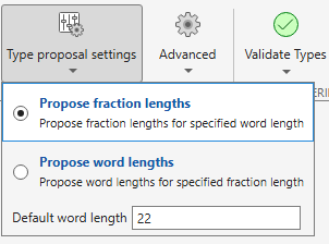
Propose fraction lengths for a given fixed word length setting.
Propose word lengths for a given fixed fraction length setting.
When you start with a floating-point design and convert to a fixed-point design for the first time, start by specifying a value for Default Word Length. Set the word length based on the largest dynamic range of all the variables in the design.
For this example, enter a default word length of 22. To specify the default word length, select Propose fraction lengths.
Understand Proposed Types
The type table contains this following information for each variable in the floating-point MATLAB design, organized by function:
Sim Min: Minimum value assigned to the variable during simulation
Sim Max: Maximum value assigned to the variable during simulation
Whole Number: Whether all values assigned during simulation are integer
The type proposal step combines with the word length settings you specify to propose a fixed-point type for each variable.
This table shows numeric type proposals for a Default word length value of 22 bits.
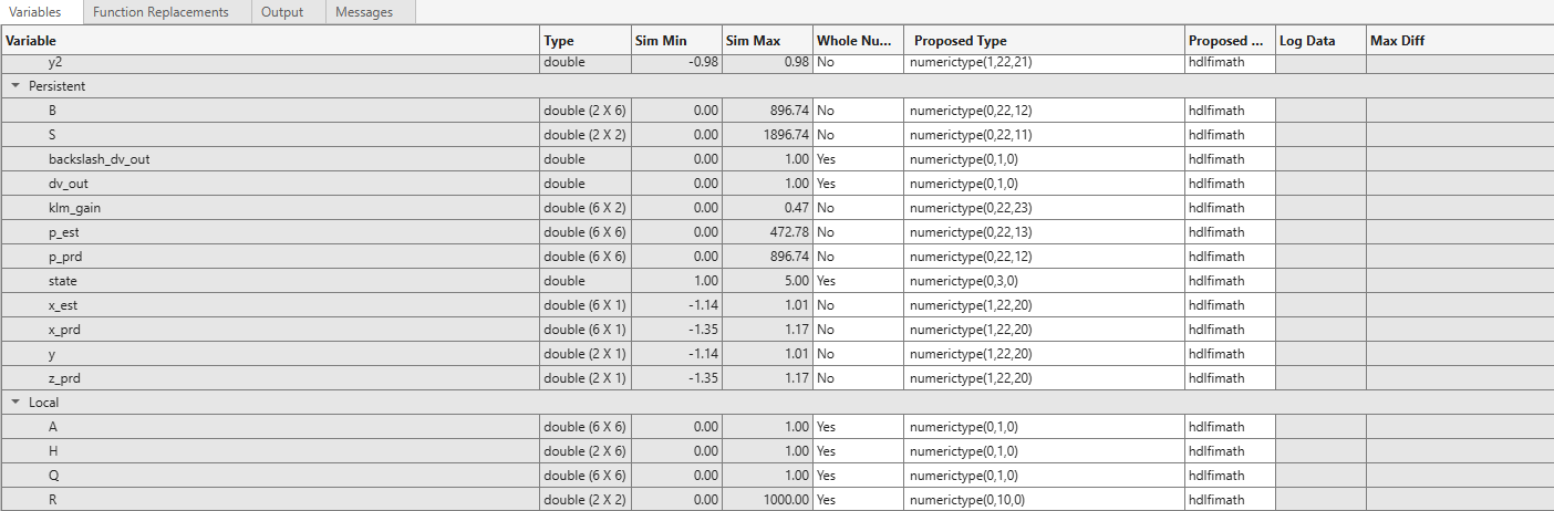
Review the types proposed in the table for variables instrumented in the top-level design.
The floating-point range for variable B:
Has the same number of bits as Default word length
Uses the minimum number of bits to completely represent the range
Uses the rest of the bits to represent the precision
The integer range for variable A:
Has the minimum number of bits to represent the whole integer range
Has no fractional bits
You can edit proposed types directly in the table. All information in the table persists across iterations and is saved with your code generation project.
Generate and Verify Code
Use the proposed data types for a default word length of 22 to generate and verify the fixed-point code.
To apply computed fixed-point types click Validate Types.
Under Plotting and Reporting, in the Test Numerics list, select
Log inputs and outputs for comparison plots.To run the test bench with the fixed-point code click the Test Numerics button.
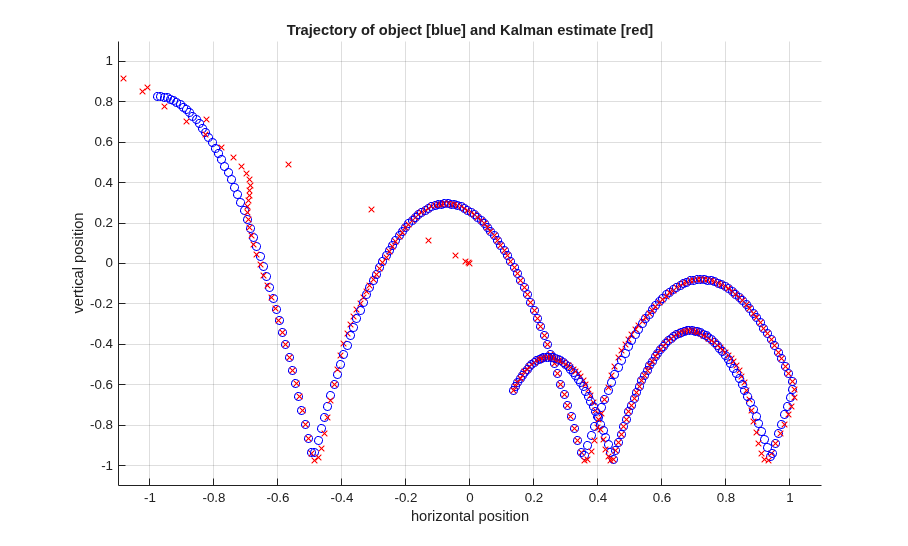
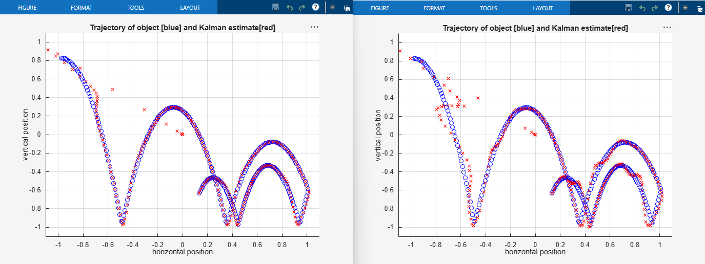
The plot on the left is generated from running the test bench during the simulation of floating-point code. The plot on the right is generated from simulating the generated fixed-point code. The plots do not match.
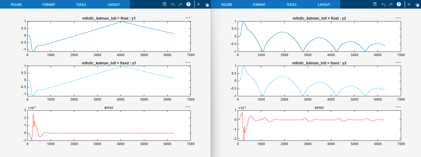
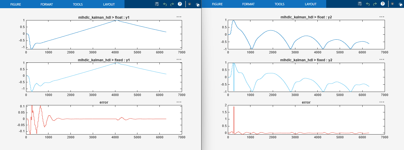
The tool also generates comparison plots for each output variable. The comparison plots show the floating-point output, fixed-point output, and error between the two outputs for the variables y1 and y2.
Iterate on the Results
The error graph shows significant error between the floating-point output and fixed-point output when the the word length set to 22 bits. This error occurs because the word length for the fixed-point design does not provide the necessary precision to represent all the values in the range of the floating-point output. To reduce the error, increase the value of Default word length and repeat the fixed-point conversion.
Set Default word length to 28. Changing the default word length automatically triggers the type proposal step, and the tool proposes new fixed-point types based on the new word length setting. To regenerate the comparison plots with the new proposed types, repeat the type validation and numeric testing.
Click Validate Types.
To rerun the test bench on the fixed-point code, click the Test Numerics button.
Once these steps are complete, review the comparison plots for y1 and y2. The error is now smaller.