Implement an Audio Filter on an Intel Board
In this example, we illustrate how to:
Model an audio system with Low pass and Band pass filters
Implement it on a Intel® board using an audio reference design

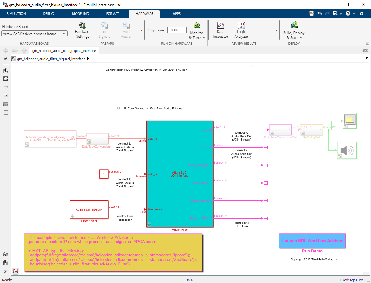
The objective of this example is to receive audio input through Arrow SoC Development Kit's line input, process it on the FPGA and transmit the processed audio to a speaker. The above figure shows the high-level architecture of such a system. It uses an audio codec to interface to the peripherals and to convert analog to digital signals and vice-versa. The Audio Codec IPs are used to configure the audio codec and for transferring audio data between Intel SoC and audio codec. The Filter IP is used for audio processing. ARM processor is used to control the type of filter to be used i.e. low pass or band pass.
Before You Begin
To run this example, you must have the following software and hardware installed and set up:
HDL Coder™ Support Package for Intel FPGA and SoC Devices
Embedded Coder® Support Package for Intel SoC Devices
Intel Quartus® Prime Standard, with supported version listed in HDL Language Support and Supported Third-Party Tools and Hardware
Intel SoC Embedded Design Suite
Arrow SoC Development Kit
To setup the Arrow SoC Development Kit, refer to the Set up Intel SoC hardware and tools section in the Get Started with IP Core Generation for Intel SoC Devices example. Connect an audio input from a mobile or an MP3 player to LINE IN jack and either earphones or speakers to LINE OUT jack on the Arrow SoC as shown below.

Introduction
In the following model, an audio file is used as input to the DUT subsystem, Audio_filter. On simulating this model in Simulink, the processed audio effect can be heard through the Audio Device Writer block and Spectrum Analyzer block displays the spectrogram of the filtered audio output.
modelname = 'hdlcoder_audio_filter_biquad';
open_system(modelname);

Model a System with Low pass and Band pass Filters
The Filter Designer (DSP System Toolbox) app in Simulink generates the filter coefficients. In this model, the app generates the filter coefficients for each type of filter. The model then exports these coefficients and stores them in a MATLAB file. It uses these coefficients to design filters in Simulink. In this model, discrete IIR filter blocks from Simulink implement Biquad low pass or band pass filters, depending on the corresponding filter coefficients.
You can test this model by simulating the model in Simulink. The range of frequencies seen on the Spectrum Analyzer and the audio effect heard through the Audio Device Writer block should vary depending on the type of filter selected. The Filter Select block is used to select the type of filtering to be done on the audio input.
Customize the Model for Arrow SoC Development Kit
In order to implement this model on Arrow SoC, you must first create a reference design in Qsys which receives audio input on Arrow SoC and transmits the processed audio data out of Arrow SoC. For details on how to create a reference design which integrates the audio filter model, refer to Author Audio System Reference Design for Basic Intel Evaluation Board example.
In the reference design, left and right channel audio data are combined to form a single channel. They are concatenated such that lower 24 bits is the left channel and upper 24 bits is the right channel. In the Simulink model shown above, Data_in is split into 2 channels i.e. left and right accordingly. Their magnitude is divided by 2 and the 2 channels are added together to form a single channel. Filtering is done on this channel.
Data_in and Valid_in are the AXI4-Stream signals. Data_in contains the audio data to be processed and Valid_in acts as the enable signal. Each filter is mapped to an LED on Arrow SoC to visually indicate whether the filter is on or off.
FilterSelect input is controlled via AXI4 interface.
Generate HDL IP core with AXI4-Stream Interface
Next, you can start the HDL Workflow Advisor and use the Intel® hardware-software co-design workflow to deploy this design on the Intel hardware. For a more detailed step-by-step guide, you can refer to the Get Started with IP Core Generation for Intel SoC Devices example.
1. Set up the Intel Quartus synthesis tool path using the hdlsetuptoolpath command in the MATLAB command window. Use your own Intel Quartus installation path when you run the command. For example:
hdlsetuptoolpath('ToolName', 'Altera Quartus II', 'ToolPath', quartuspath);
2. Add both the IP repository folder and the Arrow SoC Development Kit registration file to the MATLAB path using following commands:
example_root = (hdlcoder_intel_examples_root)
cd (example_root)
addpath(genpath('ipcore'));
addpath(genpath('ArrowSoC'));
3. Start the HDL Workflow Advisor from the DUT subsystem, hdlcoder_audio_filter_biquad/Audio_filter or by double-clicking the Launch HDL Workflow Advisor box in the model.
In Task 1.1, select IP Core Generation for Target workflow, and select Arrow SoC Development Kit for Target platform.
In Task 1.2, Audio System with AXI4 Stream Interface is selected for Reference Design.

The AXI4-Stream interface is used for transferring audio data between the reference design and the filtering algorithm IP. The AXI4-Stream interface contains data (Data) and control signals such as data valid (Valid), back pressure (Ready), and data boundary (TLAST). At least Data and Valid signals are required for AXI4-Stream IP core generation. In Task 1.3, the Target platform interface table is loaded as shown in the following picture. The audio data stream ports, Valid_in, Data_in, Valid_out and Data_out,are mapped to the AXI4-Stream interfaces, Pass_through_LED, BiQuad_LPF_LED, BiQuad_BPF_LED are mapped to the LEDs on Arrow SoC and the control parameter port Filter_select is mapped to the AXI4 interface.
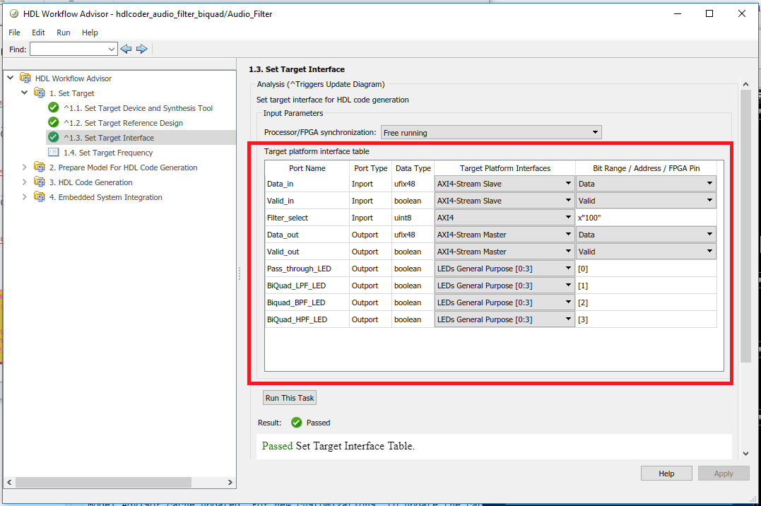
The AXI4-Stream interface communicates in master/slave mode, where the master device sends data to the slave device. Therefore, if a data port is an input port, assign it to an AXI4-Stream Slave interface, and if a data port is output port, assign it to an AXI4-Stream Master interface.
3. Right-click Task 3.2, Generate RTL Code and IP Core, and select Run to Selected Task to generate the IP core. You can find the register address mapping and other documentation for the IP core in the generated IP Core Report.
Integrate IP Into AXI4-Stream Audio Compatible Reference Design
Next, in the HDL Workflow Advisor, you run the Embedded System Integration tasks to deploy the generated HDL IP core on Intel SoC.
1. Run Task 4.1, Create Project. This task inserts the generated IP core into the Audio System with AXI4 Stream Interface reference design. As shown in the first diagram, this reference design contains the IPs to handle audio data in and out of Arrow SOC. The generated project is a complete design, including the algorithm part (the generated DUT algorithm IP), and the platform part (the reference design). For details on how to create a reference design which integrates the audio filter model, refer to Author Audio System Reference Design for Basic Intel Evaluation Board example.
2. Click on the Generated Altera Qsys project link in the Result pane to open the generated platform designer Qsys project.

3. In the HDL Workflow Advisor, run the rest of the tasks to generate the software interface model, and build and download the FPGA bitstream. Choose Download programming method in the task Program Target Device to download the FPGA bitstream onto the SD card on the Intel board, so your design will be automatically reloaded when you power cycle the Intel board.

Generate ARM executable to Tune Parameters on the FPGA Fabric
A software interface model is generated in Task 4.2, Generate Software Interface Model.
1. Before you generate code from the software interface model, comment out the audio input source and audio output sink i.e. From Multimedia File, Data Type Conversion, Buffer, Audio Device Writer and Spectrum Analyzer Blocks. These blocks do not need to be run on the ARM processor. The Audio_filter IP is running as Filtering_Algorithm on FPGA fabric. The ARM processor is using AXI4 interface for selecting the filter type i.e. Biquad Low pass, Band pass or Pass Through.
In the generated model, go to Hardware pane and then open the Configuration Parameters dialog box by clicking on Hardware Settings.
Select Solver and set Stop Time to inf.
Then in the Hardware Pane, Click on Monitor & Tune button. Embedded Coder builds the model, downloads the ARM executable to the Intel board hardware, executes it, and connects the model to the executable running on the Intel board hardware. Then you can tune model parameters.
The type of filter to be used can be selected using the drop down options in Filter Select block

The filtered audio output can be heard by plugging earphones or speakers to LINE OUT jack on the Arrow SoC. Depending on the filter selected, the corresponding LED on the Arrow SoC turns on. In this example, LD0 turns on when Pass through (No filter used) option is selected, LD1 turns on when Biquad Low pass filter is selected, LD2 turns on when Biquad Band pass filter is selected.