Timing Offset Estimation
This example shows how to generate HDL code from a basic lead-lag timing offset estimation algorithm implemented in MATLAB® code.
Introduction
In wireless communication systems, receive data is oversampled at the RF front end. This serves several purposes, including providing sufficient sampling rates for receive filtering.
However, one of the most important functions is to provide multiple sampling points on the received waveform such that data can be sampled near the maximum amplitude point in the received waveform. This example illustrates a basic lead-lag time offset estimation core, operating recursively.
The generated hardware core for this design operates at 1/os_rate where os_rate is the oversampled rate. That is, for 8 oversampled clock cycles this core iterates once. The output is at the symbol rate.
design_name = 'mlhdlc_comms_toe';
testbench_name = 'mlhdlc_comms_toe_tb';
Let us take a look at the MATLAB® design.
type(design_name);
%%%%%%%%%%%%%%%%%%%%%%%%%%%%%%%%%%%%%%%%%%%%%%%%%%%%%%%%%%%%%%%%%%%%%%%%%%%
% MATLAB design: Time Offset Estimation
%
%% Introduction:
%
% The generated hardware core for this design operates at 1/os_rate
% where os_rate is the oversampled rate. That is, for 8 oversampled clock cycles
% this core iterates once. The output is at the symbol rate.
%
% Key design pattern covered in this example:
% (1) Data is sent in a vector format, stored in a register and accessed
% multiple times
% (2) The core also illustrates basic mathematical operations
%

%   Copyright 2011-2015 The MathWorks, Inc.

%#codegen
function [tauh,q] = mlhdlc_comms_toe(r,mu)

persistent tau
persistent rBuf

os_rate = 8;
if isempty(tau)
    tau = 0;
    rBuf = zeros(1,3*os_rate);
end

rBuf = [rBuf(1+os_rate:end) r];

taur = round(tau);

% Determine lead/lag values and compute offset error
zl = rBuf(os_rate+taur-1);
zo = rBuf(os_rate+taur);
ze = rBuf(os_rate+taur+1);
offsetError = zo*(ze-zl);

% update tau
tau = tau + mu*offsetError;

tauh = tau;

q = zo;
type(testbench_name);
function mlhdlc_comms_toe_tb
%
% Copyright 2011-2015 The MathWorks, Inc.
os_rate = 8;
Ns = 128;
SNR = 100;
mu = .5; % smoothing factor for time offset estimates
% create simulated signal
rng('default'); % always default to known state
b = round(rand(1,Ns));
d = reshape(repmat(b*2-1,os_rate,1),1,Ns*os_rate);
x = [zeros(1,Ns*os_rate) d zeros(1,Ns*os_rate)];
y = awgn(x,SNR);
w = fir1(3*os_rate+1,1/os_rate)';
z = filter(w,1,y);
r = z(4:end); % give it an offset to make things interesting
%tau = 0;
Nsym = floor(length(r)/os_rate);
tauh = zeros(1,Nsym-1); q = zeros(1,Nsym-1);
for i1 = 1:Nsym-1
rVec = r(1+(i1-1)*os_rate:i1*os_rate);
% Call to the Timing Offset Estimation Algorithm
[tauh(i1),q(i1)] = mlhdlc_comms_toe(rVec,mu);
end
indexes = 1:os_rate:length(tauh)*os_rate;
indexes = indexes+tauh+os_rate-1-os_rate*2;
Fig1Loc=figposition([5 50 90 40]);
H_f1=figure(1); clf;
set(H_f1,'position',Fig1Loc);
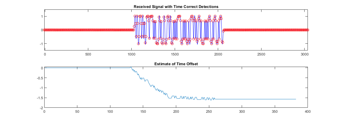
subplot(2,1,1)
plot(r,'b');
hold on
plot(indexes,q,'ro');
axis([indexes(1) indexes(end) -1.5 1.5]);
title('Received Signal with Time Correct Detections');
subplot(2,1,2)
plot(tauh);
title('Estimate of Time Offset');
function y=figposition(x)
%FIGPOSITION Positions figure window irrespective of the screen resolution
% Y=FIGPOSITION(X) generates a vector the size of X.
% This specifies the location of the figure window in pixels
%
screenRes=get(0,'ScreenSize');
% Convert x to pixels
y(1,1)=(x(1,1)*screenRes(1,3))/100;
y(1,2)=(x(1,2)*screenRes(1,4))/100;
y(1,3)=(x(1,3)*screenRes(1,3))/100;
y(1,4)=(x(1,4)*screenRes(1,4))/100;
Simulate the Design
It is always a good practice to simulate the design with the testbench prior to code generation to make sure there are no runtime errors.
mlhdlc_comms_toe_tb
Create a New HDL Coder™ Project
coder -hdlcoder -new mlhdlc_toe
Next, add the file mlhdlc_comms_toe.m to the project as the MATLAB Function and mlhdlc_comms_toe_tb.m as the MATLAB Test Bench.
Refer to Generate HDL Code from MATLAB Algorithms for a more complete tutorial on creating and populating MATLAB HDL Coder projects.
Run Fixed-Point Conversion and HDL Code Generation
Launch the Workflow Advisor from the Workflow Advisor button and right-click on the Code Generation step and choose the option Run to selected task to run all the steps from the beginning through the HDL code generation.
Examine the generated HDL code by clicking on the hyperlinks in the Code Generation Log window.