Poppet with Seat at B (IL-PB)
R2026bPoppet with Seat at B (IL-PB) block

To add a block to a model, double-click the canvas and start typing the block name. Then, select the block from the list.
Libraries:
Simscape /
Fluids /
Isothermal Liquid /
Valves & Orifices /
Hydromechanical Valves
Description
The Poppet with Seat at B (IL-PB) block represents a poppet and valve seat with the poppet at port B. The metering area increases as the poppet moves in the positive direction relative to the valve seat, which is toward port F. This movement creates a flow path between ports Af and B. To model this component with the poppet on the opposite side, use the Poppet with Seat at F (IL-PB) block.
Use the Flow momentum force model parameter to specify the method the
block uses to calculate the flow momentum force. The block always models the pressure
force. When you select Liquid flows around poppet to port F, the
block calculates the pressure force by multiplying by the seat area by the fluid
pressure difference across the block. Otherwise, the block calculates the pressure force
from the seat area and the gauge pressure at B.fluid. A positive
fluid force pushes the poppet in the positive direction, and a negative fluid force
pushes the poppet in the negative direction.
Port Relations
Ports F and B are hydromechanical valve
composite ports that have valve_body, spool,
and fluid nodes, where:
The position of
B.valve_bodyis equal to the position ofF.valve_body.The position of
F.spoolrelative toB.spoolis equal to the value of the Poppet length along valve axis parameter.The valve lift is the position of
B.spoolrelative toB.valve_body. When the valve lift is0, a hard stop engages.
Governing Equations
The mass flow rate through the fluid flow path is
where:
Δp is the pressure differential.
Δpcrit is the critical pressure differential.
ρavg is the average fluid density.
Ar is the ratio from the metering area to the connecting area.
Cd is the value of the Discharge coefficient parameter.
A is the metering area.
The critical pressure differential is
where:
Rec is the value of the Critical Reynolds number parameter.
ν is the fluid kinematic viscosity.
When you set Flow momentum force model to Based
on poppet and seat geometry or Based on tabulated jet
angle, the flow momentum force is
where Amax is the maximum metering area
and α is the jet angle. If Flow momentum force
model is Based on poppet and seat
geometry, the block calculates α depending on the
block geometry. If Flow momentum force model is
Based on tabulated jet
					angle
, the block interpolates
α from the Poppet lift vector for jet
angle, Jet angle vector for inflow through seat,
and Jet angle vector for outflow through seat
parameters.
When you set Flow momentum force model to
None, FFlow
is 0. However, the block still models the pressure force.
Metering Area
The metering area depends on the poppet and seat geometry.
When Poppet geometry is
Conical, the metering area for both seat
geometries is
where:
γ is the value of the Poppet cone angle parameter.
ds is the value of the Seat hole diameter parameter.
x is the lift between poppet and seat.
The maximum metering area is
The maximum metering area occurs when the valve lift is greater than or equal to
The jet angle is ɑ = γ/2.
When Poppet geometry is
Cylindrical and Seat
geometry is Sharp-edged, the metering
area is
The maximum metering area is
The maximum metering area occurs when the valve lift is greater than or equal to xmax = ds/4. The block assumes that the jet angle is 90°.
When Poppet geometry is
Cylindrical and Seat
geometry is Conical, the metering area
is
where dp is the value of the Poppet diameter parameter.
The maximum metering area is
The maximum metering area occurs when the valve lift is greater than or equal to
The jet angle is ɑ = γ/2.
When Poppet geometry is
Spherical and Seat geometry
is Sharp-edged, the metering area is
where:
rs is the seat radius.
rp is the poppet radius.
The maximum metering area is
The maximum metering area occurs when the valve lift is greater than or equal to
The jet angle is
When Poppet geometry is
Spherical and Seat geometry
is Conical, the metering area equations vary
depending on the expression
If the metering area and maximum metering area are
The maximum metering area occurs when the valve lift is greater than or equal to
The jet angle is ɑ = γ/2.
If the metering area and maximum metering area are
where
The jet angle is
Block Sub-Components
The Poppet with Seat at B (IL-PB) block is equivalent to a composite component that comprises these Simscape Foundation and Fluids library blocks:
This image shows the equivalent diagram when you select Liquid flows around poppet to port F:

This image shows the equivalent diagram when you clear Liquid flows around poppet to port F:

Variables
To set the priority and initial target values for the block variables prior to simulation, use the Initial Targets section in the block dialog box or Property Inspector. For more information, see Set Priority and Initial Target for Block Variables.
Nominal values provide a way to specify the expected magnitude of a variable in a model. Using system scaling based on nominal values increases the simulation robustness. Nominal values can come from different sources, one of which is the Nominal Values section in the block dialog box or Property Inspector. For more information, see Modify Nominal Values for a Block Variable.
Examples
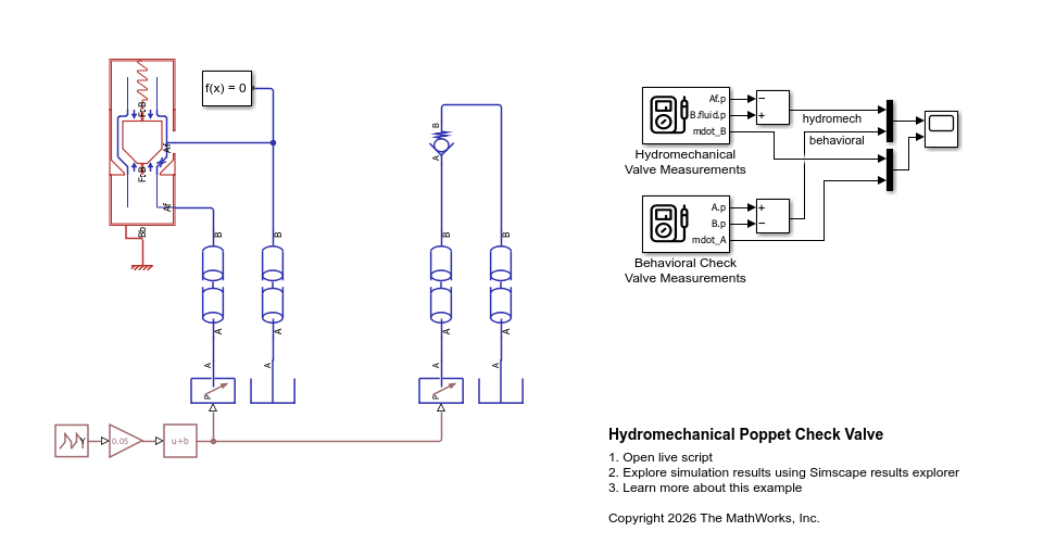
Hydromechanical Poppet Check Valve
Build a check valve with a poppet design using components from the Hydromechanical Valves library and compares it to the behavioral Check Valve (IL) block.
Ports
Conserving
Parameters
References
[1] Manring, Noah D. Hydraulic Control Systems. John Wiley & Sons, 2005.
[2] Merritt, Herbert E. Hydraulic Control Systems. John Wiley & Sons, 1967.
Extended Capabilities
Version History
Introduced in R2026b

