Contenido principal

Valve Section with Valve Port (IL-PB)

R2026b

Valve section with valve port for hydromechanical valves

Since R2026b

  • block icon

Libraries:
Simscape / Fluids / Isothermal Liquid / Valves & Orifices / Hydromechanical Valves

Description

The Valve Section with Valve Port (IL-PB) block represents a valve port and with metered flow. A land can move to meter flow from either side B or F. This block does not model the land that meters the flow. You must connect this block to a Valve Port with Land Edge at F (IL-PB), Valve Port with Land Edge at B (IL-PB), or Valve Port with Land (IL-PB) block to model the land. When you connect one of these blocks to the Valve Section with Valve Port (IL-PB) block, the same land can meter flow in multiple ports. To model a land that only meters flow in this block and not an additional valve port, connect a Valve Piston (IL-PB) block.

Use the Flow momentum force model (side B) or Flow momentum force model (side F) parameter to specify the method the block uses to calculate the flow momentum force.

Port Relations

Ports F and B are hydromechanical valve composite ports that have valve_body, spool, and fluid nodes, where:

  • The position of F.spool relative to B.spool is the value of the Shaft length between two land edges.

  • The liquid volume is V=A∗L, where L is the value of the Shaft length between two land edges parameter and A is the value of the Liquid cross-sectional area in valve section parameter.

The opening distance on the B side is the position of B.spool relative to the valve port edge on the F side. The opening distance on the F side is the position of F.spool relative to the valve port edge on the B side. If Metering edge geometry is Sharp Edge, the flow path is closed at an opening distance of 0. If Metering edge geometry is Chamfer, the flow path is fully closed when the opening distance is equal to the negative of the value of the Chamfer setback parameter, on the respective side.

This figure shows the geometric relationships of the port nodes. An adjacent block must model the land shown in the figure. Use the Valve Port with Land Edge at F (IL-PB), Valve Port with Land Edge at B (IL-PB), Valve Port with Land (IL-PB), or Valve Piston (IL-PB).

Metering Area

The metering area depends on the metering edge and valve port geometry and which side is metering the flow.

Sharp Edge Metering Edge

When Metering edge geometry for the metering side is Sharp Edge and Valve port geometry is Regular slot, the metering area and maximum metering area are

A=xlpAmax=wplp

where:

  • x is the distance between the port edge and the land piston face.

  • lp is the value of the Port length along valve circumference parameter.

  • wp is the value of the Port width along valve axis parameter.

When Valve port geometry is Round holes, the metering area and maximum metering area are

A=npdp24[(2xdp−1)1−(2xdp−1)2+arcsin(2xdp−1)+π2]Amax=npπdp24

where:

  • np is the value of the Number of holes along valve circumference parameter.

  • dp is the value of the Hole diameter parameter.

Chamfer Metering Edge

When Metering edge geometry for the metering side is Chamfer and Valve port geometry is Regular slot, the metering area and maximum metering area are

A={(x+wc)lpsinθc,  x≤wctan2θclpx2+(wctanθc)2,  wctan2θc<x≤wp−wclpx2+[(wp−x)tanθc]2,  x>wp−wcAmax=wplp

where:

  • wc is the value of the Chamfer setback along valve axis parameter.

  • θc is the value of the Chamfer angle with respect to valve axis parameter.

When Valve port geometry is Round holes, the metering area and maximum metering area are

A={npdp2sinθc4[(2xc1dp−1)1−(2xc1dp−1)2+arcsin(2xc1dp−1)+π2],  x≤wctan2θcnpdp2sinθc24[(2xc22dpx−1)1−(2xc22dpx−1)2+arcsin(2xc22dpx−1)+π2],  wctan2θc<x≤wp−wcnpdp2sinθc34[(2xc32dpx−1)1−(2xc32dpx−1)2+arcsin(2xc32dpx−1)+π2],  x>wp−wcAmax=npπdp24

where:

xc1=x+wcxc2=x2+(wctanθc)2xc3=x2+[(wp−x)tanθc]2sinθc2=xx2+(wctanθc)2sinθc3=xx2+[(wp−x)tanθc]2

Tabulated Metering Area

When Metering edge geometry for the metering side is Tabulated metering area, the block uses a lookup table to determine the metering area from the Opening distance vector and Metering area vector parameters.

Jet Angle Calculations and Flow Effects

When Flow momentum force model for the metering side is None, the block does not include the flow momentum force. However, it does model the pressure force.

When Flow momentum force model for the metering side is Based on von Mises jet angle, the jet angle is

cosα=cosαmetering+cosαcracking−cosαmetering1+0.642(x¯c)1.26

where:

  • αcracking is the value of the Cracking jet angle for valve port inflow or Cracking jet angle for valve port outflow parameter, depending on the direction of the flow at port Af.

  • αmetering is the value of the Metering jet angle for valve port inflow or Metering jet angle for valve port outflow parameter, depending on the direction of the flow at port Af.

  • x¯ is the distance between the port edge and the land piston face, except when Metering edge geometry is Chamfer. In that case, x¯= x+wc.

When the opening moves beyond the fully open or fully closed positions, the block smoothly transitions the jet angle to 90° over a distance of 0.1 multiplied by the value of either the Port width along valve axis or Hole diameter parameter. Because of the jet angle saturation, the flow momentum force smoothly transitions to zero when the land edge moves away from the valve port.

The block does not modify the jet angle calculation for metering edge geometry modifications such as chamfers because the geometry and fluid jet interaction is too complex to approximate with a lumped parameter model. If your system uses machined geometry modifications to the land edge to mitigate the flow momentum force, estimate the jet angle empirically by either fitting the von Mises jet angle parameterization or using the tabulated parameterization.

When Flow momentum force model for the metering side is Based on tabulated jet angle, the block calculates the jet angle by using a lookup table from the Opening distance vector for jet angle parameter and either the Jet angle vector for valve port inflow or Jet angle vector for valve port outflow parameter, depending on the direction of the flow at port Af.

When the land is metering the flow from the F side, the flow momentum force is

Fflow=−m˙2ρ(cosαA).

When the land is metering the flow from the B side, the flow momentum force is

Fflow=m˙2ρ(cosαA).

Mass Flow Rate

The mass flow rate through the fluid flow path is

m˙=Δp(Δp2+Δpcrit2)1/4(2ρavg1-Ar2)1/2CdA,

where:

  • Δp is the pressure differential.

  • Δpcrit is the critical pressure differential.

  • ρavg is the average fluid density.

  • Ar is the ratio from the metering area to the connecting area.

  • Cd is the value of the Discharge coefficient parameter.

  • A is the metering area.

The critical pressure differential is

Δpcrit=π4ρavg2A(RecνCd)2,

where:

  • Rec is the value of the Critical Reynolds number parameter.

  • ν is the fluid kinematic viscosity.

Block Sub-Components

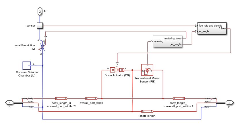
The Valve Section with Valve Port (IL-PB) block is equivalent to a composite component that comprises these Simscape Foundation and Fluids library blocks:

This image shows the equivalent diagram when the land is metering the flow from the B side:
system screenshot

This image shows the equivalent diagram when the land is metering the flow from the F side:

system screenshot

Variables

To set the priority and initial target values for the block variables prior to simulation, use the Initial Targets section in the block dialog box or Property Inspector. For more information, see Set Priority and Initial Target for Block Variables.

Nominal values provide a way to specify the expected magnitude of a variable in a model. Using system scaling based on nominal values increases the simulation robustness. Nominal values can come from different sources, one of which is the Nominal Values section in the block dialog box or Property Inspector. For more information, see Modify Nominal Values for a Block Variable.

Examples
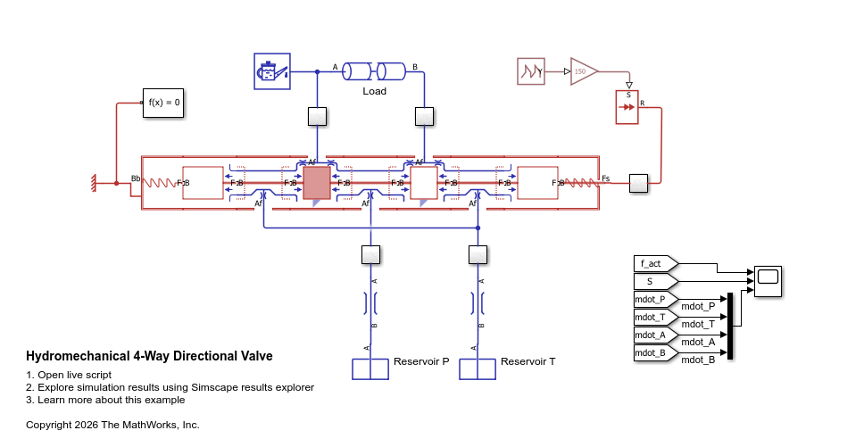
Ports

Conserving

expand all

Hydromechanical valve composite port that comprises three nodes:

  • B.valve_body — Position-based translational node along the valve body. The distance between this node and the center of the valve port is equal to the value of the Valve body length between B and center of valve port parameter.

  • B.spool — Position-based translational node along the moving spool. This node represents the land edge.

  • B.fluid — Isothermal liquid node associated with the flow path inside the valve. This node represents the fluid flow to an adjacent valve component.

Programmatic Use

Port: B

Hydromechanical valve composite port that comprises three nodes:

  • F.valve_body — Position-based translational node along the valve body. The distance between this node and the center of the valve port is equal to the value of the Valve body length between F and center of valve port parameter.

  • F.spool — Position-based translational node along the moving spool. This node represents the land edge.

  • F.fluid — Isothermal liquid node associated with the flow path inside the valve. This node represents the fluid flow to an adjacent valve component.

Programmatic Use

Port: F

Isothermal liquid conserving port associated with the port on the valve body.

Programmatic Use

Port: Af

Parameters

expand all

Valve Section

Length of the valve body between port B and the center of the valve port, defined along the direction of the valve axis.

Programmatic Use

Parameter: body_length_B

Length of the valve body between port F and the center of the valve port, defined along the direction of the valve axis.

Programmatic Use

Parameter: body_length_F

Length of the shaft between the two land edges, defined along the direction of the valve axis.

Programmatic Use

Parameter: shaft_length

Cross-sectional area of the liquid in the valve section.

Programmatic Use

Parameter: section_area

Whether to model the dynamic compressibility of the liquid. Dynamic compressibility affects the transient response of the system at small timescales. If you select this parameter, the pressure responds dynamically based on the accumulation of fluid mass in the volume. If you clear this parameter, the volume does not accumulate mass and the pressure response is instantaneous. Clearing this setting can improve simulation performance, but may have a negative effect on the simulation robustness. Only clear this setting for small fluid volumes or models with long simulation times.

Programmatic Use

Parameter: enable_dynamic_compressibility
Values: "true" | "false"

Pressure for the isothermal liquid at the start of the simulation.

Dependencies

To enable this parameter, select Enable fluid dynamic compressibility.

Programmatic Use

Parameter: p_init

Flow Metering

Shape of the metering edge at side B.

Programmatic Use

Parameter: metering_geometry_B
Values: "fluids.isothermal_liquid.valves_orifices.hydromechanical_valves.enum.MeteringGeometry.SharpEdge" | "fluids.isothermal_liquid.valves_orifices.hydromechanical_valves.enum.MeteringGeometry.Chamfer" | "fluids.isothermal_liquid.valves_orifices.hydromechanical_valves.enum.MeteringGeometry.TabulatedMetering"

Chamfer setback in the direction along the valve axis at side B. If the spool moves in the horizontal direction, this parameter is in the horizontal direction.

This value is wc in this diagram:

Dependencies

To enable this parameter, set Metering edge geometry (side B) to Chamfer.

Programmatic Use

Parameter: chamfer_setback_B

Chamfer angle measured with respect to the valve axis at side B. If the spool moves in the horizontal direction, this parameter is measured with respect to the horizontal.

This value is θc in this diagram:

Dependencies

To enable this parameter, set Metering edge geometry (side B) to Chamfer.

Programmatic Use

Parameter: chamfer_angle_B

Opening distance values that correspond to the values in the Metering area vector (side B) parameter.

Dependencies

To enable this parameter, set Metering edge geometry (side B) to Tabulated metering area.

Programmatic Use

Parameter: opening_TLU_B

Metering area values that correspond to the values in the Opening distance vector (side B) parameter.

Dependencies

To enable this parameter, set Metering edge geometry (side B) to Tabulated metering area.

Programmatic Use

Parameter: area_TLU_B

Shape of the metering edge at side F.

Programmatic Use

Parameter: metering_geometry_F
Values: "fluids.isothermal_liquid.valves_orifices.hydromechanical_valves.enum.MeteringGeometry.SharpEdge" | "fluids.isothermal_liquid.valves_orifices.hydromechanical_valves.enum.MeteringGeometry.Chamfer" | "fluids.isothermal_liquid.valves_orifices.hydromechanical_valves.enum.MeteringGeometry.TabulatedMetering"

Chamfer setback in the direction along the valve axis at side F. If the spool moves in the horizontal direction, this parameter is in the horizontal direction.

This value is wc in this diagram:

Dependencies

To enable this parameter, set Metering edge geometry (side F) to Chamfer.

Programmatic Use

Parameter: chamfer_setback_F

Chamfer angle measured with respect to the valve axis at side F. If the spool moves in the horizontal direction, this parameter is measured with respect to the horizontal.

This value is θc in this diagram:

Dependencies

To enable this parameter, set Metering edge geometry (side F) to Chamfer.

Programmatic Use

Parameter: chamfer_angle_F

Opening distance values that correspond to the values in the Metering area vector (side F) parameter.

Dependencies

To enable this parameter, set Metering edge geometry (side F) to Tabulated metering area.

Programmatic Use

Parameter: opening_TLU_F

Metering area values that correspond to the values in the Opening distance vector (side F) parameter.

Dependencies

To enable this parameter, set Metering edge geometry (side F) to Tabulated metering area.

Programmatic Use

Parameter: area_TLU_F

Shape of valve ports. When you select Rectangular slot, the block models one rectangular port. When you select Round holes, the block models multiple holes around the circumference of the valve.

Dependencies

To enable this parameter, set Metering edge geometry (side B) or Metering edge geometry (side F) to Sharp Edge or Chamfer.

Programmatic Use

Parameter: port_geometry
Values: "fluids.isothermal_liquid.valves_orifices.hydromechanical_valves.enum.PortGeometry.RectangularSlot" | "fluids.isothermal_liquid.valves_orifices.hydromechanical_valves.enum.PortGeometry.RoundHoles"

Width of the rectangular valve port, defined along the direction of the valve axis.

Dependencies

To enable this parameter, set Metering edge geometry (side B) or Metering edge geometry (side F) to Tabulated metering area, or set Metering edge geometry (side B) or Metering edge geometry (side F) to Sharp Edge or Chamfer and Valve port geometry to Rectangular slot.

Programmatic Use

Parameter: port_width

Length of the rectangular valve port, defined along the direction of the valve circumference.

Dependencies

To enable this parameter, set Metering edge geometry (side B) or Metering edge geometry (side F) to Sharp Edge or Chamfer and set Valve port geometry to Rectangular slot.

Programmatic Use

Parameter: port_length

Diameter of each hole along the valve circumference.

Dependencies

To enable this parameter, set Metering edge geometry (side B) or Metering edge geometry (side F) to Sharp Edge or Chamfer and set Valve port geometry to Round holes.

Programmatic Use

Parameter: hole_diameter

Number of holes. The holes are evenly spaced around the circumference of the valve.

Dependencies

To enable this parameter, set Metering edge geometry (side B) or Metering edge geometry (side F) to Sharp Edge or Chamfer and set Valve port geometry to Round holes.

Programmatic Use

Parameter: num_holes

Ratio of the minimum metering area to the maximum metering area. The block uses this parameter to calculate the minimum metering area.

Dependencies

To enable this parameter, set Metering edge geometry (side B) or Metering edge geometry (side F) to Sharp Edge or Chamfer.

Programmatic Use

Parameter: min_area_fraction

Cross-sectional area of the fluid channel at the location of the valve port.

Programmatic Use

Parameter: connecting_area

Correction factor that accounts for discharge losses in theoretical flows.

Programmatic Use

Parameter: Cd

Upper Reynolds number limit for laminar flow through the component.

Programmatic Use

Parameter: Re_c

Flow Effects

Method for modeling flow momentum force on the land at side B. If you select None, the block does not model flow momentum force on the land at side B.

Programmatic Use

Parameter: flow_force_model_B
Values: "fluids.isothermal_liquid.valves_orifices.hydromechanical_valves.enum.SpoolFlowForceModel.None" | "fluids.isothermal_liquid.valves_orifices.hydromechanical_valves.enum.SpoolFlowForceModel.VonMisesJetAngle" | "fluids.isothermal_liquid.valves_orifices.hydromechanical_valves.enum.SpoolFlowForceModel.TabulatedJetAngle"

Jet angle for the inflow through the port when the valve begins to open at side B. The value of this parameter must be less than or equal to the value of the Metering jet angle for valve port inflow (side B) parameter.

Dependencies

To enable this parameter, set Flow momentum force model (side B) to Based on von Mises jet angle.

Programmatic Use

Parameter: jet_angle_cracking_inflow_B

Jet angle for the inflow through the port when the valve operates in the metering region at side B. The value of this parameter must be greater than or equal to the value of the Cracking jet angle for valve port inflow (side B) parameter.

Dependencies

To enable this parameter, set Flow momentum force model (side B) to Based on von Mises jet angle.

Programmatic Use

Parameter: jet_angle_metering_inflow_B

Jet angle for the outflow through the port when the valve begins to open at side B. The value of this parameter must be less than or equal to the value of the Metering jet angle for valve port outflow (side B) parameter.

Dependencies

To enable this parameter, set Flow momentum force model (side B) to Based on von Mises jet angle.

Programmatic Use

Parameter: jet_angle_cracking_outflow_B

Jet angle for the outflow through the port when the valve operates in the metering region at side B. The value of this parameter must be greater than or equal to the value of the Cracking jet angle for valve port outflow (side B) parameter.

Dependencies

To enable this parameter, set Flow momentum force model (side B) to Based on von Mises jet angle.

Programmatic Use

Parameter: jet_angle_metering_outflow_B

Opening distance values for the jet angle values for inflow and outflow through the valve at side B.

Dependencies

To enable this parameter, set Flow momentum force model (side B) to Based on tabulated jet angle.

Programmatic Use

Parameter: opening_jet_TLU_B

Jet angle values for inflow through the valve at side B. These values correspond to the values in the Opening distance vector for jet angle (side B) parameter. If the last element is not 90, the flow momentum force continues to be nonzero for any opening larger than the table range.

Dependencies

To enable this parameter, set Flow momentum force model (side B) to Based on tabulated jet angle.

Programmatic Use

Parameter: jet_angle_inflow_TLU_B

Jet angle values for outflow through the valve at side B. These values correspond to the values in the Opening distance vector for jet angle (side B) parameter. If the last element is not 90, the flow momentum force continues to be nonzero for any opening larger than the table range.

Dependencies

To enable this parameter, set Flow momentum force model (side B) to Based on tabulated jet angle.

Programmatic Use

Parameter: jet_angle_outflow_TLU_B

Method for modeling flow momentum force on the land at side F. If you select None, the block does not model flow momentum force on the land at side F.

Programmatic Use

Parameter: flow_force_model_F
Values: "fluids.isothermal_liquid.valves_orifices.hydromechanical_valves.enum.SpoolFlowForceModel.None" | "fluids.isothermal_liquid.valves_orifices.hydromechanical_valves.enum.SpoolFlowForceModel.VonMisesJetAngle" | "fluids.isothermal_liquid.valves_orifices.hydromechanical_valves.enum.SpoolFlowForceModel.TabulatedJetAngle"

Jet angle for the inflow through the port when the valve begins to open at side F. The value of this parameter must be less than or equal to the value of the Metering jet angle for valve port inflow (side F) parameter.

Dependencies

To enable this parameter, set Flow momentum force model (side F) to Based on von Mises jet angle.

Programmatic Use

Parameter: jet_angle_cracking_inflow_F

Jet angle for the inflow through the port when the valve operates in the metering region at side F. The value of this parameter must be greater than or equal to the value of the Cracking jet angle for valve port inflow (side F) parameter.

Dependencies

To enable this parameter, set Flow momentum force model (side F) to Based on von Mises jet angle.

Programmatic Use

Parameter: jet_angle_metering_inflow_F

Jet angle for the outflow through the port when the valve begins to open at side F. The value of this parameter must be less than or equal to the value of the Metering jet angle for valve port outflow (side F) parameter.

Dependencies

To enable this parameter, set Flow momentum force model (side F) to Based on von Mises jet angle.

Programmatic Use

Parameter: jet_angle_cracking_outflow_F

Jet angle for the outflow through the port when the valve operates in the metering region at side F. The value of this parameter must be greater than or equal to the value of the Cracking jet angle for valve port outflow (side F) parameter.

Dependencies

To enable this parameter, set Flow momentum force model (side F) to Based on von Mises jet angle.

Programmatic Use

Parameter: jet_angle_metering_outflow_F

Opening distance values for the jet angle values for inflow and outflow through the valve at side F.

Dependencies

To enable this parameter, set Flow momentum force model (side F) to Based on tabulated jet angle.

Programmatic Use

Parameter: opening_jet_TLU_F

Jet angle values for inflow through the valve at side F. These values correspond to the values in the Opening distance vector for jet angle (side F) parameter. If the last element is not 90, the flow momentum force continues to be nonzero for any opening larger than the table range.

Dependencies

To enable this parameter, set Flow momentum force model (side F) to Based on tabulated jet angle.

Programmatic Use

Parameter: jet_angle_inflow_TLU_F

Jet angle values for outflow through the valve at side F. These values correspond to the values in the Opening distance vector for jet angle (side F) parameter. If the last element is not 90, the flow momentum force continues to be nonzero for any opening larger than the table range.

Dependencies

To enable this parameter, set Flow momentum force model (side F) to Based on tabulated jet angle.

Programmatic Use

Parameter: jet_angle_outflow_TLU_F

Distance between the land outer land edge and the valve body, defined along the radial direction.

Dependencies

To enable this parameter, set Flow momentum force model (side B) or Flow momentum force model (side F) to Based on von Mises jet angle.

Programmatic Use

Parameter: radial_clearance

Plots

Use the Plot button to generate the metering area plot.

Use the Plot button to generate the jet angle plot. To generate a plot, you must set Flow momentum force model (side B) or Flow momentum force model (side F) to Based on von Mises jet angle or Based on tabulated jet angle.

References

[1] Manring, Noah D. Hydraulic Control Systems. John Wiley & Sons, 2005.

[2] Merritt, Herbert E. Hydraulic Control Systems. John Wiley & Sons, 1967.

[3] von Mises, R., 1917. Berechnung von Ausfluß und uberfallzahlen. VDI, (22), pp.469-474.

Extended Capabilities

expand all

C/C++ Code Generation
Generate C and C++ code using Simulink® Coder™.

Version History

Introduced in R2026b