Gerotor Pump
R2026bThis example shows how to model, parameterize, and test a gerotor pump.
Model
The following figure shows a model of the gerotor pump with a lubrication system. The flow circuit consists of an inlet system upstream of the pump, the gerotor pump and a load system downstream of the pump.
open_system('GerotorPump')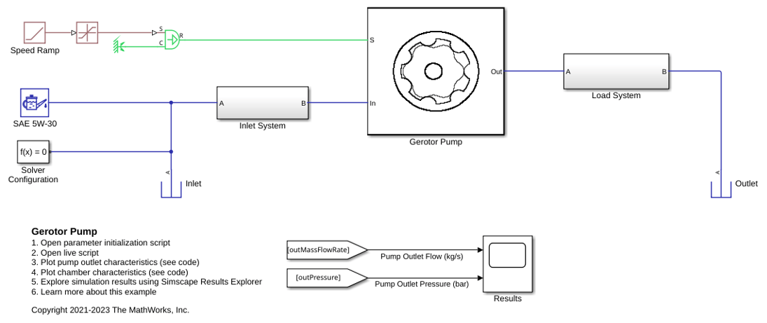
Geometrical parameters of the gear set are required to model the variation of each chamber volume with shaft rotation. After determining the geometrical parameters, you can generate the variation of volume of any chamber with shaft rotation or the volume profile. Also, you can obtain the derivative of volume for respective chambers with angle of rotation. These two profiles are required for simulation and can be provided rather than deriving from geometrical parameters.
A custom Simscape component models the variable volume liquid chamber. The chamber is connected to two mechanical rotating conserving ports to calculate angular velocity and a isothermal liquid port. The isothermal liquid port A for a liquid chamber connects to an inlet port orifice and an outlet port orifice. These orifices represent the inlet and outlet port opening area that the chamber is exposed to as the pump rotates and are also modeled with a custom Simscape component. This component connects to two isothermal liquid ports and one rotational angle port. The variation of inlet and outlet orifice area for any chamber with shaft rotation must be provided by the user.
Examine the Gerotor Pump Subsystem
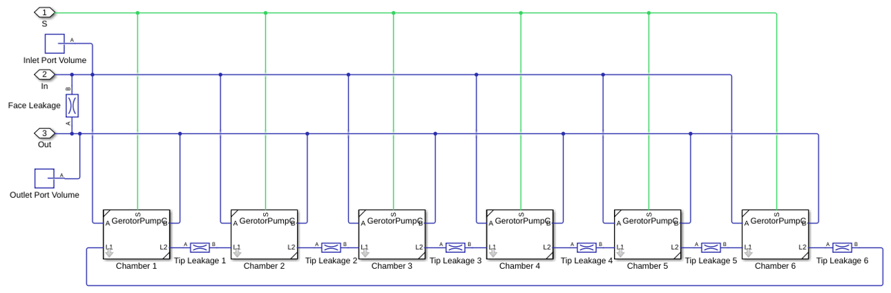
This subsystem shows how the gerotor pump is modeled. The gerotor pump comprises of an outer gear (driven gear) and an inner gear (driving gear) mounted on a rotating shaft, modeled as an angular velocity source. For this pump, the inner gear teeth profile is based on a trochoid curve geometry, and the outer gear teeth profile is a conjugate of the inner gear teeth profile. A gerotor pump is a positive displacement type pump, as the volumetric flow is effectively produced by the continual suction and delivery actions performed by the cyclical variation of the volume between the teeth of the mating gear set. This liquid volume between the mating gears can be divided into a number of sub-volumes or chambers which are connected with the adjacent ones through a gap due to teeth (or tip) clearance leading to tip leakage between chambers. The inlet and outlet port volumes are connected through a leakage flow called face leakage resulting from the clearance between the gear faces and housing inner faces. The volumes of the chambers change as the pump rotates and they are connected to the inlet port volume and outlet port volume through port area profiles. The number of variable volume liquid chambers equal the number of outer gear teeth.
Examine the Inlet and Load System Subsystems
This subsystem shows a representation of an inlet system or suction system upstream of a gerotor pump. The inlet system is modeled using a combination of pipes, bends, sudden area changes and an orifice representing a pressure drop across a filter. These components contribute to pressure drop upstream of the pump.

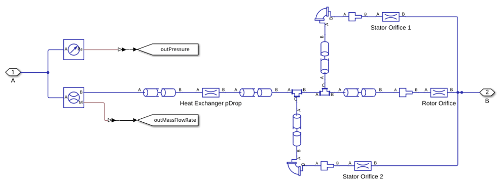
This subsystem shows a representation of a lubrication and cooling system in an automotive where a motor is lubricated and cooled by the delivery flow of a gerotor pump. The load system is modeled using a combination of pipes, bends, sudden area changes, and orifices representing the pressure drop across a heat exchanger and orifices at entry to stator and rotor. All components contribute to load system pressure drop. The thermal effects are not considered in this model as it is purely isothermal.
Equations of the System
The geometrical parameters of a gerotor pump used to calculate the derived parameters are shown in the figure above.
The equations for a particular liquid chamber are shown below. Only the equations of fluid dynamics of the system is shown and the mechanics part is not shown.
where:
is the instantaneous area of i-th chamber
is the instantaneous volume of i-th chamber
is the instantaneous density of i-th chamber
is the instantaneous liquid mass of i-th chamber
is the instantaneous pressure of i-th chamber
is eccentricity between two gears
is the number of teeth of outer gear (driven gear)
is gear width
is trochoid coefficient, and can be calculated as where d is distance between fixed center of outer gear and , the epitrochoid generating point
is equidistant coefficient, and can be calculated as , where is radius of the equidistant
is radius of outer gear root circle
is rotation angle of trochoid coordinate system for i-th chamber, and can be calculated as , where
Model Results
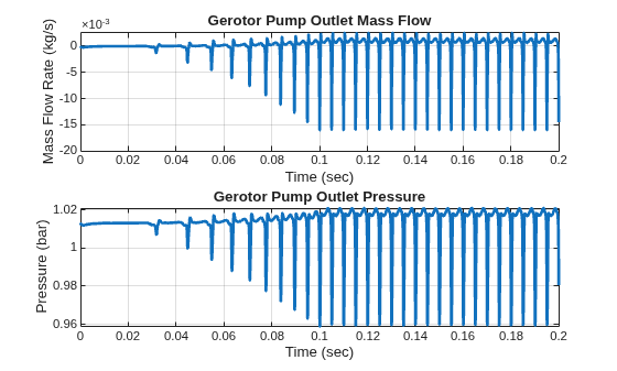
Run the model and plot the mass flow rate and pressure at the outlet of the gerotor pump versus time.
simT = 0.2; % Simulation time
sim('GerotorPump',simT)
GerotorPumpPlotCharacteristics;