Synchronization Signals (PSS and SSS)
In LTE, there are two downlink synchronization signals which are used by the UE to obtain the cell identity and frame timing.
Primary synchronization signal (PSS)
Secondary synchronization signal (SSS)
The division into two signals is aimed to reduce the complexity of the cell search process.
Cell Identity Arrangement
The physical cell identity, , is defined by the equation:
is the physical layer cell identity group (0 to 167).
is the identity within the group (0 to 2).
This arrangement creates 504 unique physical cell identities.
Synchronization Signals and Determining Cell Identity
The primary synchronization signal (PSS) is linked to the cell identity within the group (). The secondary synchronization signal (SSS) is linked to the cell identity group () and the cell identity within the group ().
You can obtain by successfully demodulating the PSS. The SSS can then be demodulated and combined with knowledge of to obtain . Once you establish the values of and , you can determine the cell identity ().
Primary Synchronization Signal (PSS)
The primary synchronization signal (PSS) is based on a frequency-domain Zadoff-Chu sequence.
Zadoff-Chu Sequences
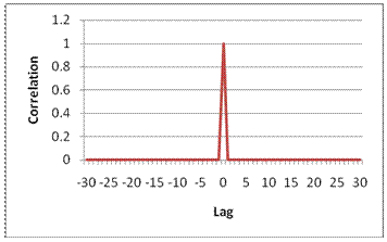
Zadoff-Chu sequences are a construction of Frank-Zadoff sequences defined by D. C. Chu in [1]. These codes have the useful property of having zero cyclic autocorrelation at all nonzero lags. When used as a synchronization code, the correlation between the ideal sequence and a received sequence is greatest when the lag is zero. When there is any lag between the two sequences, the correlation is zero. This property is illustrated in this figure.
PSS Generation
The PSS is a sequence of complex symbols, 62 symbols long.
The sequence used for the PSS is generated according to these equations:
In the preceding equation, u is the Zadoff-Chu root sequence index and depends on the cell identity within the group .
| Root index u | |
|---|---|
| 0 | 25 |
| 1 | 29 |
| 2 | 34 |
Mapping of the PSS
The PSS is mapped into the first 31 subcarriers either side of the DC subcarrier. Therefore, the PSS uses six resource blocks with five reserved subcarriers each side, as shown in this figure.
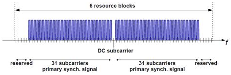
As the DC subcarrier contains no information in LTE this corresponds to mapping onto the middle 62 subcarriers within an OFDM symbol in a resource grid. d(n) is mapped from lowest subcarrier to highest subcarrier. The PSS is mapped to different OFDM symbols depending on which frame type is used. Frame type 1 is frequency division duplex (FDD), and frame type 2 is time division duplex (TDD).
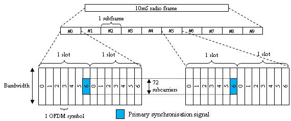
FDD — The PSS is mapped to the last OFDM symbol in slots 0 and 10, as shown in this figure.
TDD — The PSS is mapped to the third OFDM symbol in subframes 1 and 6, as shown in this figure.

Secondary Synchronization Signal (SSS)
The secondary synchronization signal (SSS) is based on maximum length sequences (m-sequences).
M-Sequence Definition
An m-sequence is a pseudorandom binary sequence which can be created by cycling through every possible state of a shift register of length m, resulting in a sequence of length 2m–1. Three m-sequences, each of length 31, are used to generate the synchronization signals denoted , and .
SSS Generation
Two binary sequences, each of length 31, are used to generate the SSS. Sequences s0(m0) and s1(m1) are different cyclic shifts of an m-sequence, . The indices m0 and m1 are derived from the cell-identity group, NID(2) and determine the cyclic shift. The values can be read from table 6.11.2.1-1 in [2].
The two sequences are scrambled with a binary scrambling code (c0(n), c1(n)), which depends on NID(2).
The second SSS sequence used in each radio frame is scrambled with a binary scrambling code (z1(m0), z1(m1)) corresponding to the cyclic shift value of the first sequence transmitted in the radio frame.
Binary Sequence Generation
The sequences s0(m0) and s1(m1) are given by these equations:
is generated from the primitive polynomial over the finite field GF(2).
c0(n) and c1(n are given by these equations:
is generated from the primitive polynomial over the finite field GF(2).
z1(m0) and z1(m1) are given by these equations:
is generated from the primitive polynomial over the finite field GF(2).
Mapping of the SSS
The scrambled sequences are interleaved to alternate the sequence transmitted in the first and second SSS transmission in each radio frame. This allows the receiver to determine the frame timing from observing only one of the two sequences; if the first SSS signal observed is in subframe 0 or subframe 5, synchronization can be achieved when the SSS signal is observed in subframe 0 or subframe 5 of the next frame.
As with PSS, the SSS is mapped to different OFDM symbols depending on which frame type is used:
FDD — The SSS is transmitted in the same subframe as the PSS but one OFDM symbol earlier. The SSS is mapped to the same subcarriers (middle 72 subcarriers) as the PSS.
TDD — The SSS is mapped to the last OFDM symbol in slots 1 and 11, which is three OFDM symbols before the PSS.
The SSS is constructed using different scrambling sequences when mapped to even and odd resource elements.
Even resource elements:
Subframe 0:
Subframe 5:
Odd resource elements:
Subframe 0:
Subframe 5:
d(n) is mapped from lowest subcarrier to highest subcarrier.
References
[1] Chu, D. C. “Polyphase codes with good periodic correlation properties.” IEEE Trans. Inf. Theory. Vol. 18, Number 4, July 1972, pp. 531–532.
[2] 3GPP TS 36.211. “Evolved Universal Terrestrial Radio Access (E-UTRA); Physical Channels and Modulation.” 3rd Generation Partnership Project; Technical Specification Group Radio Access Network. URL: https://www.3gpp.org.
See Also
ltePSS | ltePSSIndices | lteSSS | lteSSSIndices | lteCellSearch | lteDLFrameOffset | lteDLResourceGrid | zadoffChuSeq