Main Content

phased.WidebandBackscatterRadarTarget

Backscatter wideband signal from radar target

Description

The phased.WidebandBackscatterRadarTarget System object™ models backscattering of a wideband signal from a target. Backscattering is a special case of radar target scattering where the incident and reflected angles are the same. Use this object for monostatic radar configurations. The radar cross-section determines the backscattering response of a target to an incoming signal. This System object lets you specify an angle-dependent radar cross-section model that covers a range of incident angles. The wideband signal is decomposed into frequency subbands which are backscattered independently and then recombined.

This System object creates a backscattered signal for polarized or nonpolarized signals. Although electromagnetic radar signals are polarized, you can often ignore polarization in your simulation and process the signals as scalars. To ignore polarization, specify the EnablePolarization property as false. To employ polarization, specify EnablePolarization as true.

For nonpolarized signals, specify the radar cross section (RCS) as an array of values at discrete azimuth and elevation angles and discrete frequencies. The System object interpolates values for incident angles between array points. For polarized signals, specify the radar scattering matrix (SCM) using three arrays defined at discrete azimuth and elevation angles and discrete frequencies. These three arrays correspond to the HH, HV, and VV polarization components. The VH component is computed by applying the conjugate symmetry property of the HV component. H and V stand for the horizontal and vertical polarization components, respectively.

For both nonpolarized and polarized signals, you can employ one of four Swerling models to generate random fluctuations in the RCS or radar scattering matrix. Choose the model using the Model property. Then, use the SeedSource and Seed properties to randomize the fluctuations.

EnablePolarizationRadar cross-section patterns
false

RCSPattern

trueShhPattern, SvvPattern, and ShvPattern

To perform wideband target backscattering:

  1. Create the phased.WidebandBackscatterRadarTarget object and set its properties.

  2. Call the object with arguments, as if it were a function.

To learn more about how System objects work, see What Are System Objects?

Creation

Description

target = phased.WidebandBackscatterRadarTarget creates a wideband backscatter radar target System object, .

example

target = phased.WidebandBackscatterRadarTarget(Name,Value) creates a wideband backscatter radar target object, with each specified property Name set to the specified Value. You can specify additional name and value pair arguments in any order as (Name1,Value1,...,NameN,ValueN).

example

Properties

expand all

Unless otherwise indicated, properties are nontunable, which means you cannot change their values after calling the object. Objects lock when you call them, and the release function unlocks them.

If a property is tunable, you can change its value at any time.

For more information on changing property values, see System Design in MATLAB Using System Objects.

Option to enable processing of polarized signals, specified as false or true. Set this property to true to allow the target to simulate the reflection of polarized radiation. Set this property to false to ignore polarization.

Example: true

Specify the wideband backscatter pattern frequencies used in the RCS or SCM matrices. The elements of this vector must be in strictly increasing order. The target has no response outside this frequency range. Frequencies are defined with respect to the physical frequency band, not the baseband. Frequency units are in hertz.

Example: [1e3,1e10]

Azimuth angles used to define the angular coordinates of each column of the matrices specified by the RCSPattern, ShhPattern, ShvPattern, or SvvPattern properties. Specify the azimuth angles as a length P vector. P must be greater than two. Angle units are in degrees.

Example: [-45:0.1:45]

Data Types: double

Elevation angles used to define the angular coordinates of each row of the matrices specified by the RCSPattern, ShhPattern, ShvPattern, or SvvPattern properties. Specify the elevation angles as a length Q vector. Q must be greater than two. Angle units are in degrees.

Example: [-30:0.1:30]

Data Types: double

Radar cross-section pattern, specified as a real-valued matrix or array.

DimensionsApplication
Q-by-P matrixSpecifies a matrix of RCS values as a function of Q elevation angles and P azimuth angles. The same RCS matrix is used for all frequencies.
Q-by-P-by-K arraySpecifies an array of RCS patterns as a function of Q elevation angles, P azimuth angles, and K frequencies. If K = 1, the RCS pattern is equivalent to a Q-by-P matrix.
1-by-P-by-K arraySpecifies a matrix of RCS values as a function of P azimuth angles and K frequencies. These dimension formats apply when there is only one elevation angle.
K-by-P matrix

  • Q is the length of the vector specified by the ElevationAngles property.

  • P is the length of the vector specified by the AzimuthAngles property.

  • K is the number of frequencies specified by the FrequencyVector property.

You can specify patterns for L targets by putting L patterns into a cell array. All patterns must have the same dimensions. The value of L must match the column dimensions of the signals passed as input into the function. However, you can use one pattern to model L targets.

RCS units are in square meters.

Example: [1,1;1,1]

Dependencies

To enable this property, set the EnablePolarization property to false.

Data Types: double

Radar scattering matrix (SCM) HH polarization component, specified as a complex-valued matrix or array.

DimensionsApplication
Q-by-P matrixSpecifies the scattering matrix polarization component as a function of Q elevation angles and P azimuth angles. The same SCM matrix is used for all frequencies.
Q-by-P-by-K arraySpecifies the scattering matrix polarization component as a function of Q elevation angles, P azimuth angles, and K frequencies. If K = 1, the RCS pattern is equivalent to a Q-by-P matrix.
1-by-P-by-K arraySpecifies the scattering matrix polarization component as a function of P azimuth angles and K frequencies. These dimension formats apply when there is only one elevation angle.
K-by-P matrix

  • Q is the length of the vector specified by the ElevationAngles property.

  • P is the length of the vector specified by the AzimuthAngles property.

  • K is the number of frequencies specified by the FrequencyVector property.

You can specify polarization component patterns for L targets by putting L patterns into a cell array. All patterns must have the same dimensions. The value of L must match the column dimensions of the signals passed as input into the function. You can, however, use one pattern to model L targets.

SCM units are in square-meters.

Example: [1,1;1i,1i]

Dependencies

To enable this property, set the EnablePolarization property to true.

Data Types: double
Complex Number Support: Yes

Radar scattering matrix VV-pol component, specified as a complex-valued vector, matrix, or array. Different dimension cases have different applications.

DimensionsApplication
Q-by-P matrixSpecifies the scattering matrix polarization component as a function of Q elevation angles and P azimuth angles. The same SCM matrix is used for all frequencies.
Q-by-P-by-K arraySpecifies the scattering matrix polarization component as a function of Q elevation angles, P azimuth angles, and K frequencies. If K = 1, the RCS pattern is equivalent to a Q-by-P matrix.
1-by-P-by-K arraySpecifies the scattering matrix polarization component as a function of P azimuth angles and K frequencies. These dimension formats apply when there is only one elevation angle.
K-by-P matrix

  • Q is the length of the vector specified by the ElevationAngles property.

  • P is the length of the vector specified by the AzimuthAngles property.

  • K is the number of frequencies specified by the FrequencyVector property.

You can specify polarization component patterns for L targets by putting L patterns into a cell array. All patterns must have the same dimensions. The value of L must match the column dimensions of the signals passed as input into the function. You can, however, use one pattern to model L targets.

SCM units are in square-meters.

Example: [1,1;1i,1i]

Dependencies

To enable this property, set the EnablePolarization property to true.

Data Types: double
Complex Number Support: Yes

Radar scattering matrix (SCM) HV-pol component, specified as a complex-valued vector, matrix, or array. Different dimension cases have different applications.

DimensionsApplication
Q-by-P matrixSpecifies the scattering matrix polarization component as a function of Q elevation angles and P azimuth angles. The same SCM matrix is used for all frequencies.
Q-by-P-by-K arraySpecifies the scattering matrix polarization component as a function of Q elevation angles, P azimuth angles, and K frequencies. If K = 1, the RCS pattern is equivalent to a Q-by-P matrix.
1-by-P-by-K arraySpecifies the scattering matrix polarization component as a function of P azimuth angles and K frequencies. These dimension formats apply when there is only one elevation angle.
K-by-P matrix

  • Q is the length of the vector specified by the ElevationAngles property.

  • P is the length of the vector specified by the AzimuthAngles property.

  • K is the number of frequencies specified by the FrequencyVector property.

You can specify polarization component patterns for L targets by putting L patterns into a cell array. All patterns must have the same dimensions. The value of L must match the column dimensions of the signals passed as input into the function. You can, however, use one pattern to model L targets.

SCM units are in square-meters.

Example: [1,1;1i,1i]

Dependencies

To enable this property, set the EnablePolarization property to true.

Data Types: double
Complex Number Support: Yes

Target fluctuation model, specified as 'Nonfluctuating', 'Swerling1', 'Swerling2', 'Swerling3', or 'Swerling4'. If you set this property to a value other than 'Nonfluctuating', use the update input argument when calling the function.

Example: 'Swerling3'

Data Types: char

Signal propagation speed, specified as a positive scalar. Units are in meters per second. The default propagation speed is the value returned by physconst('LightSpeed'). See physconst for more information.

Example: 3e8

Data Types: double

Operating frequency, specified as a positive scalar. Units are in Hz.

Example: 1e9

Data Types: double

Signal sample rate, specified as a positive real-valued scalar. Units are in hertz.

Example: 1e6

Data Types: double

Number of processing subbands, specified as a positive integer.

Example: 128

Data Types: double

Seed source of random number generator for RCS fluctuation model, specified as 'Auto' or 'Property'. When you set this property to:

  • 'Auto', the object generates random numbers using the default MATLAB® random number generator.

  • 'Property', you specify the random number generator seed using the Seed property.

When using this object with Parallel Computing Toolbox™ software, set this property to 'Auto'.

Dependencies

To enable this property, set the Model property to 'Swerling1', 'Swerling2', 'Swerling3', or 'Swerling4'.

Data Types: string

Random number generator seed, specified as a nonnegative integer less than 232. .

Example: 32301

Dependencies

To enable this property, set the SeedSource property to 'Property'.

Data Types: double

Usage

Description

refl_sig = target(sig,ang) returns the reflected signal, refl_sig, of an incident nonpolarized signal, sig. This syntax applies when you set the EnablePolarization property to false and the Model property to 'Nonfluctuating'. In this case, the values specified in the RCSPattern property are used to compute the RCS values for the incident and reflected directions, ang.

example

refl_sig = target(sig,ang,update) uses update to control whether to update the RCS values. This syntax applies when you set the EnablePolarization property to false and the Model property to one of the fluctuating RCS models: 'Swerling1', 'Swerling2', 'Swerling3', or 'Swerling4'. If update is true, a new RCS value is generated. If update is false, the previous RCS value is used.

example

refl_sig = target(sig,ang,laxes) returns the reflected signal, refl_sig, of an incident polarized signal, sig. This syntax applies when you set EnablePolarization to true and the Model property to 'Nonfluctuating'. The values specified in the ShhPattern, SvvPattern, and ShvPattern properties are used to compute the backscattering matrices for the incident directions, ang. The laxes argument specifies a local coordinate system used to define the horizontal and vertical polarization components.

refl_sig = target(sig,ang,laxes,update) uses the update argument to control whether to update the scattering matrix values. This syntax applies when you set the EnablePolarization property to true and the Model property to one of the fluctuating RCS models: 'Swerling1', 'Swerling2', 'Swerling3', or 'Swerling4'. If update is true, a new RCS value is generated. If update is false, the previous RCS value is used.

Input Arguments

expand all

  • Wideband nonpolarized signal, specified as an N-by-M complex-valued matrix. The quantity N is the number of signal samples and M is the number of independent signals reflecting off the target. Each column contains an independent signal reflected from the target.

    The size of the first dimension of the input matrix can vary to simulate a changing signal length. A size change can occur, for example, in the case of a pulse waveform with variable pulse repetition frequency.

  • Wideband polarized signal, specified as a 1-by-M struct array containing complex-valued fields. Each struct element contains three N-by-1 column vectors of electromagnetic field components (sig.X,sig.Y,sig.Z) representing the polarized signal that reflects from the target. Each struct element contains three N-by-1 complex-valued column vectors, sig.X, sig.Y, and sig.Z. These vectors represent the x, y, and z Cartesian components of the polarized signal.

    The size of the first dimension of the matrix fields within the struct can vary to simulate a changing signal length such as a pulse waveform with variable pulse repetition frequency.

Example: [1,1;j,1;0.5,0]

Data Types: double
Complex Number Support: Yes

Incident signal direction, specified as a real-valued column 2-by-1 vector or 2-by-M matrix. Each column of ang specifies the incident direction of the corresponding signal in the form [AzimuthAngle;ElevationAngle]. The number of columns in ang must match the number of independent signals in sig. Units are in degrees.

Example: [30;45]

Data Types: double

Option to enable the RCS values for fluctuation models to update, specified as false or true. When update is true, a new RCS value is generated with each call to the function. If update is false, the RCS remains unchanged with each call to the function.

Data Types: logical

Local coordinate system matrix, specified as a 3-by-3 real-valued orthonormal matrix or a 3-by-3-by-M real-valued array. The matrix columns specify the local coordinate system orthonormal x-axis, y-axis, and z-axis, respectively. Each axis is a vector of the form (x;y;z) with respect to the global coordinate system. When sig has only one signal, laxes is a 3-by-3 matrix. When sig has multiple signals, you can use a single 3-by-3 matrix for multiple signals in sig. In this case, all targets have the same local coordinate systems. When you specify laxes as a 3-by-3-by-M array, each page (third index) defines a 3-by-3 local coordinate matrix for the corresponding target.

Example: [1,0,0;0,0.7071,-0.7071;0,0.7071,0.7071]

Data Types: double

Output Arguments

expand all

  • Wideband nonpolarized signal, returned as an N-by-M complex-valued matrix. Each column contains an independent signal reflected from the target.

  • Wideband polarized signal, returned as a 1-by-M struct array containing complex-valued fields. Each struct element contains three N-by-1 column vectors of electromagnetic field components (sig.X,sig.Y,sig.Z) representing the polarized signal that reflects from the target.

The quantity N is the number of signal samples and M is the number of signals reflecting off the target. Each column corresponds to a reflecting angle.

For polarized fields, the struct element contains three N-by-1 complex-valued column vectors: sig.X, sig.Y, and sig.Z. These vectors represent the x, y, and z Cartesian components of the polarized signal.

The output refl_sig contains signal samples arriving at the signal destination within the current input time frame. When the propagation time from source to destination exceeds the current time frame duration, the output does not contain all contributions from the input of the current time frame. The remaining output appears in the next call to the function.

Object Functions

To use an object function, specify the System object as the first input argument. For example, to release system resources of a System object named obj, use this syntax:

release(obj)

expand all

stepRun System object algorithm
releaseRelease resources and allow changes to System object property values and input characteristics
resetReset internal states of System object

Examples

collapse all

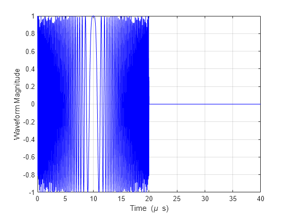
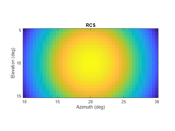
Calculate the reflected radar signal from a nonfluctuating point target having a peak RCS of 10.0 m^2. Use a simple target RCS pattern for illustrative purposes. Real RCS patterns are more complicated. The RCS pattern covers a range of angles from 10-30 degrees in azimuth and 5-15 degrees in elevation. The RCS peaks at 20 degrees azimuth and 10 degrees elevation. The RCS also has a frequency dependence and is specified at 5 frequencies within the signal bandwidth. Assume that the radar operating frequency is 100 MHz and that the signal is a linear FM waveform having a 20 MHz bandwidth.

Create and plot the wideband signal.

c = physconst('LightSpeed');
fs = 50e6;
pw = 20e-6;
PRF = 1/(2*pw);
fc = 100e6;
bw = 20e6;
waveform = phased.LinearFMWaveform('SampleRate',fs,'PulseWidth',pw, ...
    'PRF',PRF,'OutputFormat','Pulses','NumPulses',1,'SweepBandwidth',bw, ...
    'SweepDirection','Down','Envelope','Rectangular','SweepInterval', ...
    'Symmetric');
wav = waveform();
n = size(wav,1);
plot([0:(n-1)]/fs*1e6,real(wav),'b')
xlabel('Time (\mu s)')
ylabel('Waveform Magnitude')
grid

Figure contains an axes object. The axes object with xlabel Time ( mu blank s), ylabel Waveform Magnitude contains an object of type line.

Create an RCS pattern at five different frequencies within the signal bandwidth using a simplified frequency dependence. The frequency dependence is unity at the operating frequency and falls off outside that frequency. Realistic frequency dependencies are more complicated. Plot the RCS pattern for one of the frequencies.

fvec = fc + [-fs/2,-fs/4,0,fs/4,fs/2];
fdep = cos(3*(1 - fvec/fc));
azmax = 20.0;
elmax = 10.0;
azpattern = [10.0:0.5:30.0];
elpattern = [5.0:0.5:15.0];
rcspattern0 = 10.0*cosd(4*(elpattern - elmax))'*cosd(4*(azpattern - azmax));
for k = 1:5
    rcspattern(:,:,k) = rcspattern0*fdep(k);
end
imagesc(azpattern,elpattern,abs(rcspattern(:,:,1)))
axis image
axis tight
title('RCS')
xlabel('Azimuth (deg)')
ylabel('Elevation (deg)')

Figure contains an axes object. The axes object with title RCS, xlabel Azimuth (deg), ylabel Elevation (deg) contains an object of type image.

Create the phased.WidebandBackscatterRadarTarget System object™.

target = phased.WidebandBackscatterRadarTarget('Model','Nonfluctuating', ...
    'AzimuthAngles',azpattern,'ElevationAngles',elpattern,...
    'RCSPattern',rcspattern,'OperatingFrequency',fc,'NumSubbands',32, ...
    'FrequencyVector',fvec);

For a sequence of incident azimuth angles at constant elevation, find and plot the reflected signal amplitude.

az0 = 13.0;
el = 10.0;
az = az0 + [0:2:20];
naz = length(az);
magsig = zeros(1,naz);
for k = 1:naz
    y = target(wav,[az(k);el]);
    magsig(k) = max(abs(y));
end
plot(az,magsig,'r.')
xlabel('Azimuth (deg)')
ylabel('Scattered Signal Amplitude')
grid

Figure contains an axes object. The axes object with xlabel Azimuth (deg), ylabel Scattered Signal Amplitude contains a line object which displays its values using only markers.

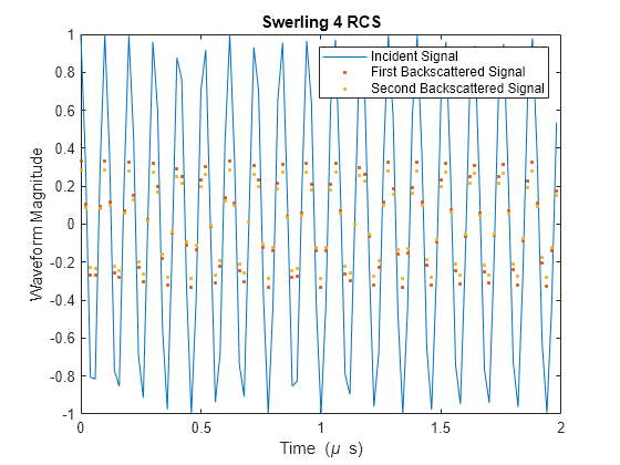
Calculate the reflected radar signal from a Swerling 4 fluctuating point target with a peak RCS of 0.1 m^2. Use a simple target RCS pattern for illustrative purposes. Real RCS patterns are more complicated. The RCS pattern covers a range of angles from 10 - 30 degrees in azimuth and 5 -15 degrees in elevation. The RCS peaks at 20 degrees in azimuth and 10 degrees in elevation at a value of 0.1 m^2. The RCS also has a frequency dependence and is specified at five frequencies within the signal bandwidth. Assume that the radar operating frequency is 100 MHz and that the signal is a linear FM waveform with a 20 MHz bandwidth. The sampling frequency is 50 MHz.

Create and plot the wideband signal.

c = physconst('LightSpeed');
fs = 50e6;
pw = 20e-6;
PRF = 1/(2*pw);
fc = 100.0e6;
bw = 20.0e6;
waveform = phased.LinearFMWaveform('SampleRate',fs,'PulseWidth',pw, ...
    'PRF',PRF,'OutputFormat','Pulses','NumPulses',1,'SweepBandwidth',bw, ...
    'SweepDirection','Down','Envelope','Rectangular','SweepInterval', ...
    'Symmetric');
wav = waveform();

Create an RCS pattern at five different frequencies within the signal bandwidth using a simple frequency dependence. The frequency dependence is designed to be unity at the operating frequency and fall off outside that band. Realistic frequency dependencies are more complicated.

fvec = fc + [-fs/2,-fs/4,0,fs/4,fs/2];
fdep = cos(3*(1 - fvec/fc));
azmax = 20.0;
elmax = 10.0;
azangs = [10.0:0.5:30.0];
elangs = [5.0:0.5:15.0];
rcspattern0 = 0.1*(cosd((elangs - elmax))'*cosd((azangs - azmax))).^2;
for k = 1:5
    rcspattern(:,:,k) = rcspattern0*fdep(k);
end
imagesc(azangs,elangs,abs(rcspattern(:,:,5)))
axis image
axis xy
axis tight
title('RCS')
xlabel('Azimuth (deg)')
ylabel('Elevation (deg)')
colorbar

Figure contains an axes object. The axes object with title RCS, xlabel Azimuth (deg), ylabel Elevation (deg) contains an object of type image.

Create the phased.WidebandBackscatterRadarTarget System object™.

target = phased.WidebandBackscatterRadarTarget('Model','Swerling4', ...
    'SeedSource','Property','Seed',100213,'AzimuthAngles',azangs, ...
    'ElevationAngles',elangs,'RCSPattern',rcspattern, ...
    'OperatingFrequency',fc,'NumSubbands',32,'FrequencyVector',fvec);

Find and plot 100 samples of the incident signal and two sequential reflected signals at 10 degrees in azimuth and 10 degrees in elevation. Update the RCS at each execution of the System object™.

az = 10.0;
el = 10.0;
refl_wav1 = target(wav,[az;el],true);
refl_wav2 = target(wav,[az;el],true);
n = 100;
plot([0:(n-1)]/fs*1e6,real(wav(1:n)))
hold on
plot([0:(n-1)]/fs*1e6,real(refl_wav1(1:n)),'.')
plot([0:(n-1)]/fs*1e6,real(refl_wav2(1:n)),'.')
hold off
legend('Incident Signal','First Backscattered Signal','Second Backscattered Signal')
xlabel('Time (\mu s)')
ylabel('Waveform Magnitude')
title('Swerling 4 RCS')

Figure contains an axes object. The axes object with title Swerling 4 RCS, xlabel Time ( mu blank s), ylabel Waveform Magnitude contains 3 objects of type line. One or more of the lines displays its values using only markers These objects represent Incident Signal, First Backscattered Signal, Second Backscattered Signal.

More About

expand all

References

[1] Mott, H. Antennas for Radar and Communications. New York: John Wiley & Sons, 1992.

[2] Richards, M. A. Fundamentals of Radar Signal Processing. New York: McGraw-Hill, 2005.

[3] Skolnik, M. Introduction to Radar Systems, 3rd Ed. New York: McGraw-Hill, 2001.

Extended Capabilities

Version History

Introduced in R2016b