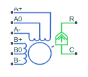
Unipolar Stepper Motor
Permanent magnet stepper motor with center taps on each of the two windings
Libraries:
Simscape /
Electrical /
Electromechanical /
Reluctance & Stepper
Description
The Unipolar Stepper Motor block models a unipolar stepper motor. Unipolar stepper motors have a permanent magnet rotor and two wound stator windings with center taps. The center taps simplify the stepper driver design because the polarity of the driver output does not need to change. If your motor does not have a center tap on each of the stator windings, use the Stepper Motor block instead.
Stepper motors with small step sizes typically have north and south pole rotors with teeth. Stepper motors with large step sizes typically have multiple magnets distributed around the rotor circumference. You can model both types of motor using the Unipolar Stepper Motor block and drive the motor using the Unipolar Stepper Motor Driver block.
You can use stepper motors to avoid the need for a position measurement. You can use stepper motors in devices such as printers and in applications like robotics and factory automation.
These equations define the winding currents and mechanical output,
where:
eA+ is the back electromotive force (EMF) induced across the A+ to A0 half-winding.
eA- is the back EMF induced across the A- to A0 half-winding.
eB+ is the back EMF induced across the B+ to B0 half-winding.
eB- is the back EMF induced across the B- to B0 half-winding.
iA+ is the current that flows from the A+ port to the A0 center tap port.
iA- is the current that flows from the A- port to the A0 center tap port.
iB+ is the current that flows from the B+ port to the B0 center tap port.
iB- is the current that flows from the B- port to the B0 center tap port.
vA+ is the voltage at the A+ port relative to the A0 center tap port.
vA- is the voltage at the A- port relative to the A0 center tap port.
vB+ is the voltage at the B+ port relative to the B0 center tap port.
vB- is the voltage at the B- port relative to the B0 center tap port.
Km is the motor torque constant.
Nr is the number of teeth on each of the two rotor poles.
R is the half-winding resistance. For example, it is the resistance between the A+ and A0 ports.
L is the half-winding inductance. For example, it is the inductance between the A+ and A0 ports.
Rm is the magnetizing resistance.
B is the rotational damping.
J is the inertia.
ω is the rotor speed.
Θ is the rotor angle.
Td is the detent torque amplitude.
Te is the electrical torque.
If the initial rotor angle is zero or a multiple of (π/2)/Nr, the rotor is aligned with the A-phase winding. If a positive current flows from the A+ port to the A0 center tap port, then the stepper acts to stay aligned with the A-phase. Equivalently, a positive current flowing from the A0 center tap port to the A- port also acts on the rotor to stay aligned with the A-phase.
The Unipolar Stepper Motor block produces a positive torque acting from the mechanical C to R ports for the four sequences listed in this table. The sequences assume the rotor initial angle is zero or a multiple of (π/2)/Nr.
| Sequence | Center Taps Connected to Ground | Center Taps Connected to Positive Supply |
|---|---|---|
| 1 | Positive current from A+ to A0 | Positive current from A0 to A- |
| 2 | Positive current from B+ to B0 | Positive current from B0 to B- |
| 3 | Positive current from A- to A0 | Positive current from A0 to A- |
| 4 | Positive current from B- to B0 | Positive current from B0 to B- |
Averaged Mode
If you set the Simulation mode parameter to
Averaged, both for a Unipolar Stepper
Motor block and for the Unipolar Stepper Motor
Driver block that controls it, then the individual steps are not
simulated. This can be a good way to speed up simulation. In Averaged mode, under
non-slipping conditions, the motor and driver are represented by a second-order
linear system that tracks the specified step rate. The demanded step rate is
determined directly from voltage across A+ and
A-. So, for example, a voltage of +10V across the
A+ and A- terminals is interpreted as
a step rate demand of ten steps per second. See the Unipolar Stepper Motor Driver reference page for more
information on how to connect the Unipolar Stepper Motor
Driver to your step angle controller.
Averaged mode includes a slip estimator to predict whether the stepper motor would have slipped if running in Stepping simulation mode. Slip is predicted if the motor torque exceeds the Vector of maximum torque values parameter value for longer than one step period, the step period being determined from the current step rate demand. Upon detecting slip, the simulation will proceed or stop with an error, according to the Action on slipping parameter value. If you choose the action that lets the simulation continue, note that simulation results may be incorrect: when slipping occurs, the torque generated by the motor will not generally be the maximum available torque; the maximum torque is only achieved if the stepper controller detects slip and adjusts the step rate command accordingly.
The dynamics of the equivalent second-order system are determined from the values that you specify for the Approximate total load inertia and Maximum step rate command parameters. It is important that you set as accurate values as possible for these parameters, so that the step rate command is tracked, and the block does not generate false slipping warnings or errors.
If you run the motor in Averaged mode with the optional thermal ports exposed (see Model Thermal Effects), then heat is added to the thermal ports assuming that the windings are always powered, even when the step rate command is zero. The block makes adjustments for half stepping and for reduced torque (and winding currents) at higher speeds. For these adjustments to be correct, the Vector of maximum torque parameter values must be correct. For half stepping, at zero speed the heat generated by the block is the average of that generated when stopped at a half step and at a full step.
If you simulate or predict slip, do some validation runs comparing Stepping and Averaged modes before using the averaged model representation for simulation studies.
Model Thermal Effects
You can expose thermal ports to model the effects of losses that convert power to heat. To expose the thermal ports, set the Modeling option parameter to either:
No thermal port— The block does not contain thermal ports.Show thermal port— The block contains multiple thermal conserving ports.
For more information about using thermal ports in actuator blocks, see Simulating Thermal Effects in Rotational and Translational Actuators.
Examples

Unipolar Stepper Motor with Control
Model a controlled permanent magnet stepper motor by using the Unipolar Stepper Motor and Unipolar Stepper Motor Driver blocks. The model has two controller options: one to control position and one to control speed. To change the controller type, right-click the Controller subsystem, select Variant > Label Mode Active Choice, and then select Position or Speed. The stepper has a full step size of 1.8 degrees. In position control mode, the input to the Ref port is the desired number of steps. In speed control mode, the input to the Ref port is the desired number of steps per second.

Unipolar Stepper Motor Averaged Mode
The Unipolar Stepper Motor simulating in Stepping and Averaged simulation modes. The purpose of Averaged mode is faster simulation for any loads that do not cause slip. To avoid incorrect interpretation of results, the stepper motor has an approximate detection of slip which can be set to generate a warning or an error.
Assumptions and Limitations
The model neglects magnetic saturation effects and any magnetic coupling between phases.
When you select the Start simulation from steady state check box in the Simscape™ Solver Configuration block, this block will not initialize an Initial rotor angle value between –π and π.
All four half-windings are assumed to be identical, and therefore have the same resistance temperature coefficient, alpha, and the same thermal mass.
To use Averaged mode, the Unipolar Stepper Motor block must be directly connected to a Unipolar Stepper Motor Driver block also running in Averaged mode.
The Averaged mode is an approximation, and exact step tracking compared to the Stepping mode should not be expected.
Slip detection in Averaged mode is approximate, and depends on a good estimate for load inertia and maximum step rate. Incorrect values may result in false slip detection.
When simulating slip in Averaged mode, it is assumed that the stepper motor controller adjusts the step rate command so as to achieve maximum possible torque.
You cannot use this block to model a hybrid stepper motor where the torque comes from both the permanent magnet and from variable reluctance effects.
Ports
Conserving
Parameters
References
[1] M. Bodson, J. N. Chiasson, R. T. Novotnak and R. B. Rekowski. “High-Performance Nonlinear Feedback Control of a Permanent Magnet Stepper Motor.” IEEE Transactions on Control Systems Technology, Vol. 1, No. 1, March 1993.
[2] P. P. Acarnley. Stepping Motors: A Guide to Modern Theory and Practice. New York: Peregrinus, 1982.
[3] S.E. Lyshevski. Electromechanical Systems, Electric Machines, and Applied Mechatronics. CRC, 1999.
Extended Capabilities
Version History
Introduced in R2012b