freeSpacePath
Syntax
Description
Examples
Calculate the free space propagation path for a radar transceiver configuration.
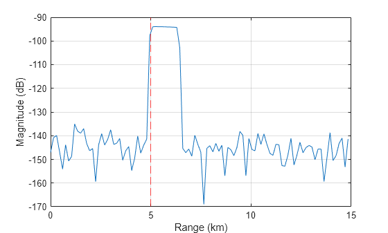
Create a radar transceiver with an isotropic antenna, transmitting a linear frequency modulated (LFM) pulse waveform with a 10 microsecond pulse width. Calculate the free space propagation paths assuming the radar is at the origin and the target is 5 km away. Return I/Q signals from the radar transceiver at the initial time and plot the results. Start by initializing the radar transceiver.
wav = phased.LinearFMWaveform(PulseWidth=1e-5); ant = phased.IsotropicAntennaElement; rdr = radarTransceiver(Waveform=wav, ... TransmitAntenna=phased.Radiator(Sensor=ant), ... ReceiveAntenna=phased.Collector(Sensor=ant), ... RangeOutputPort=true); freq = rdr.TransmitAntenna.OperatingFrequency;
Define the radar position, target position, and target velocity. Calculate the free space propagation paths. The target is located 5 km away and is moving at 20 m/s in the y-direction.
rdrPose.Position = [0 0 0]; % Radar position (m) tgtPose.Position = [0 5e3 0]; % Target position (m) tgtPose.Velocity = [0 20 0]; % Target velocity (m/s) proppaths = freeSpacePath(freq,rdrPose,tgtPose)
proppaths = struct with fields:
PathLength: 10000
PathLoss: 191.9392
ReflectionCoefficient: 11.2177
AngleOfDeparture: [2×1 double]
AngleOfArrival: [2×1 double]
DopplerShift: -40.0277
Return I/Q signals from the radarTransceiver at a time of 0 seconds and plot the results. The target is located at 5 km.
t = 0; % Time (sec) [iq,rgrid] = rdr(proppaths,t); % Plot figure plot(rgrid*1e-3,mag2db(abs(sum(iq,2)))) grid on hold on xline(5,'r--') xlabel('Range (km)') ylabel('Magnitude (dB)')

This example shows how to calculate the free space propagation path for a rotated radar transceiver configuration.
Create a radar transceiver with a directive sinc antenna with a 5 degree beamwidth. Rotate the radar to point in the direction of the target by modifying the mounting angle. Calculate the free space propagation path assuming the radar is at the origin and the target is 5 km away. The propagation paths calculated by freeSpacePath are in the radar mounting frame. Return I/Q signals from the radar transceiver at the initial time and plot the results. Start by initializing the radar transceiver.
mntAng = [90 0 0]; % Mounting angles (deg) wav = phased.LinearFMWaveform(PulseWidth=1e-5); ant = phased.IsotropicAntennaElement; rdr = radarTransceiver(Waveform=wav, ... TransmitAntenna=phased.Radiator(Sensor=ant), ... ReceiveAntenna=phased.Collector(Sensor=ant), ... RangeOutputPort=true); freq = rdr.TransmitAntenna.OperatingFrequency;
Define the radar position, target position, and target velocity. Calculate the free space propagation path in the radar mounting frame.
rdrPose.Position = [0 0 0]; % Radar position (m) tgtPose.Position = [0 5e3 0]; % Target position (m) tgtPose.Velocity = [0 20 0]; % Target velocity (m/s) proppaths = freeSpacePath(freq,rdrPose,tgtPose)
proppaths = struct with fields:
PathLength: 10000
PathLoss: 191.9392
ReflectionCoefficient: 11.2177
AngleOfDeparture: [2×1 double]
AngleOfArrival: [2×1 double]
DopplerShift: -40.0277
Return I/Q signals from radarTransceiver at a time of 0 seconds and plot the results. The target is located at 5 km.
t = 0; % Time (sec) [iq,rgrid] = rdr(proppaths,t); % Plot figure plot(rgrid*1e-3,mag2db(abs(sum(iq,2)))) grid on hold on xline(5,'r--') xlabel('Range (km)') ylabel('Magnitude (dB)')

Input Arguments
Operating frequency of the radar transceiver, specified as a positive scalar in units of hertz (Hz).
Data Types: double
Transceiver platform configuration, specified as a struct that
contains Position, Velocity, and
Orientation fields. The platform configuration is defined relative
to a global coordinate frame that is considered to have an origin at [0 0
0] in unrotated Cartesian x, y,
z coordinates (see Radar Coordinate Systems and Frames for more information on reference
frames).
| Field | Description |
|---|---|
Position | Position of the platform with respect to the global coordinate frame, specified as a
3-element row vector in the form of [ |
Velocity | Velocity of the platform with respect to the global coordinate frame, specified as a
3-element row vector in the form of [ |
Orientation | Orientation of the platform with respect to the global coordinate frame, specified as a
unitless scalar quaternion or a 3-by-3 rotation matrix in units of degrees
(deg). Orientation defines the intrinsic frame rotation from the global
coordinate frame to the current platform body frame. The default value is
|
You can define platforms as platform
objects in a radarScenario
and then return the platform poses as structs using platformPoses.
You can use a returned platform pose struct for this input argument
because it contains Position, Velocity, and
Orientation fields (irrelevant fields including
PlatformID are ignored).
Data Types: struct
Target platform configurations, specified as a struct or a
1-by-T array of structs that contain a
Position, Velocity,
Orientation, and Signatures field for each
target, T. The platform configuration is defined relative to a global
coordinate frame that is considered to have an origin at [0 0 0] in
unrotated Cartesian x, y, z
coordinates (see Radar Coordinate Systems and Frames for more information on reference
frames).
| Field | Description |
|---|---|
Position | Position of the platform with respect to the global frame, specified as a 3-element row
vector in the form of [ |
Velocity | Velocity of the platform with respect to the global frame, specified as a 3-element row
vector in the form of [ |
Orientation | Orientation of the platform with respect to the global coordinate frame, specified as a
unitless scalar quaternion or a 3-by-3 rotation matrix in units of degrees.
Orientation defines the intrinsic frame rotation from the global coordinate
frame to the current platform body frame. Units are dimensionless. The
default value is |
Signatures | Mean monostatic target radar cross section (RCS) signature, specified
as a cell array of platform signature objects. If there are multiple cells,
|
You can define platforms as platform
objects in a radarScenario
and then return the platform poses as structs using platformPoses.
You can use the returned platform pose structs for this input
argument because they contain Position, Velocity,
and Orientation fields (irrelevant fields including
PlatformID are ignored). However, the returned platform pose
structs do not contain a Signatures fields. The
Signatures field can be obtained using platformProfiles.
Data Types: struct
Name-Value Arguments
Specify optional pairs of arguments as
Name1=Value1,...,NameN=ValueN, where Name is
the argument name and Value is the corresponding value.
Name-value arguments must appear after other arguments, but the order of the
pairs does not matter.
Example: propPaths =
freeSpacePath(txPose,rxPose,tgtPoses,IncludeDirectPath=false)
Offset of the radar transceiver origin relative to the transceiver platform,
specified as a 3-element row vector in the form [x_offset y_offset
z_offset], where x_offset, y_offset,
and z_offset are offsets measured along the x-,
y-, and z-axes. The default value is
[0 0 0]. Units are in meters (m).
The transceiver platform position is set by the Position
field of the rdrPose input argument.
Data Types: double
Rotation angles of the radar transceiver mounting frame relative to the
transceiver platform body frame, specified as a 3-element row vector of intrinsic
Euler angles in the form [zyaw
ypitch xroll], where
zyaw,
ypitch, and
xroll are rotations measured about the
z-, y-, and x-axes. Units
are in degrees (deg).
Intrinsics rotations follow the right hand rule convention and are sequential:
zyaw, or yaw angle, rotates the mounting frame around the z-axis of the platform body frame.ypitch, or pitch angle, rotates the mounting frame around the y-axis of the platform body frame. This rotation is relative to the mount orientation that results from the zyaw rotation.xroll, or roll angle, rotates the mounting frame about the x-axis of the platform body frame. This rotation is relative to the mount orientation that results from the zyaw and ypitch rotations.
In other words, perform rotations in the order of yaw,
pitch, and roll on the platform
z-, y-, and x-axes to
obtain the current mounting frame axes relative to the platform body frame. The
transceiver platform orientation is set by the Orientation field
of the rdrPose input argument. See Frame Rotation (Sensor Fusion and Tracking Toolbox) for more
information on intrinsic rotations.
Data Types: double
Signal propagation speed, specified as a positive scalar. Units are in meters per
second (m/s). The default propagation speed is the value returned by
physconst("LightSpeed"). See physconst for more information.
Example: 3e8
Data Types: double
Output Arguments
Two-way monostatic free space propagation paths, returned as a
1-by-T array of path configuration structs,
where T is the number of target poses in
tgtPoses. Each propPaths
struct describes a free space, single-bounce, propagation path
between the radar transceiver transmit antenna, a target, and the radar transceiver
receive antenna, and contains these fields:
| Field | Description |
PathLength | Propagation path length, returned as a nonnegative scalar in units of meters (m). |
PathLoss | Propagation path loss, computed by summing the Free Space Path Loss along each path segment, returned as a scalar in units of decibels (dB). |
ReflectionCoefficient | Reflection coefficient, returned as a scalar in linear units. The
reflection coefficient value depends on the corresponding
|
AngleOfDeparture | Propagation path angle of departure, returned as a two-element
column vector in the form of [ |
AngleOfArrival | Propagation path angle of arrival, returned as a two-element column
vector in the form of [ |
DopplerShift | Cumulative Doppler shift along the path, returned as a scalar in units of hertz (Hz). |
Extended Capabilities
C/C++ Code Generation
Generate C and C++ code using MATLAB® Coder™.
Version History
Introduced in R2025a
See Also
radarTransceiver | rcsSignature | platform | platformPoses | platformProfiles | radarScenario
Topics
- Radar Coordinate Systems and Frames
- Frame Rotation (Sensor Fusion and Tracking Toolbox)
MATLAB Command
You clicked a link that corresponds to this MATLAB command:
Run the command by entering it in the MATLAB Command Window. Web browsers do not support MATLAB commands.
Seleccione un país/idioma
Seleccione un país/idioma para obtener contenido traducido, si está disponible, y ver eventos y ofertas de productos y servicios locales. Según su ubicación geográfica, recomendamos que seleccione: .
También puede seleccionar uno de estos países/idiomas:
Cómo obtener el mejor rendimiento
Seleccione China (en idioma chino o inglés) para obtener el mejor rendimiento. Los sitios web de otros países no están optimizados para ser accedidos desde su ubicación geográfica.
América
- América Latina (Español)
- Canada (English)
- United States (English)
Europa
- Belgium (English)
- Denmark (English)
- Deutschland (Deutsch)
- España (Español)
- Finland (English)
- France (Français)
- Ireland (English)
- Italia (Italiano)
- Luxembourg (English)
- Netherlands (English)
- Norway (English)
- Österreich (Deutsch)
- Portugal (English)
- Sweden (English)
- Switzerland
- United Kingdom (English)