Main Content

Radar Equation Calculator

Estimate maximum range, peak power, and SNR of a radar system

Since R2021a

Description

The Radar Equation Calculator app solves the basic radar equation for monostatic or bistatic radar systems. The radar equation relates target range, transmitted power, and received signal SNR. Using this app, you can:

  • Solve for maximum target range based on the transmit power of the radar and specified received SNR

  • Calculate required transmit power based on known target range and specified received SNR

  • Calculate the received SNR value based on known range and transmit power

Radar Equation Calculator app

Open the Radar Equation Calculator App

  • MATLAB® Toolstrip: On the Apps tab, under Signal Processing and Communications, click the app icon.

  • MATLAB command prompt: Enter radarEquationCalculator.

Examples

expand all

This example shows how to compute the maximum detection range of a 10 GHz, 1 kW, monostatic radar with a 40 dB antenna gain and a detection threshold of 10 dB.

From the Calculation Type drop-down list, choose Target Range as the solution.

Choose Configuration as monostatic.

Enter 40 dB for the antenna Gain.

Set the Wavelength to 3 cm.

Set the SNR detection threshold parameter to 10 dB.

Assuming the target is a large airplane, set the Target Radar Cross Section value to 100 m2.

Specify the Peak Transmit Power as 1 kW

Specify the Pulse Width as 2 µs.

Assume a total of 5 dB System Losses.

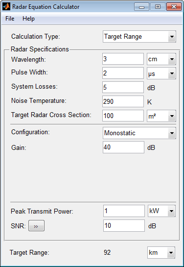
The maximum target detection range is 92 km.

This example shows how to use multiple pulses to reduce the transmitted power while maintaining the same maximum target range.

Continue with the results from the previous example.

Click the arrows to the right of the SNR label.

The Detection Specifications for SNR menu opens.

Set Probability of Detection to 0.95.

Set Probability of False Alarm to 10–6.

Set Number of Pulses to 4.

Reduce Peak Transmit Power to 0.75 kW.

Assume a nonfluctuating target model, and set the Swerling Case Number to 0.

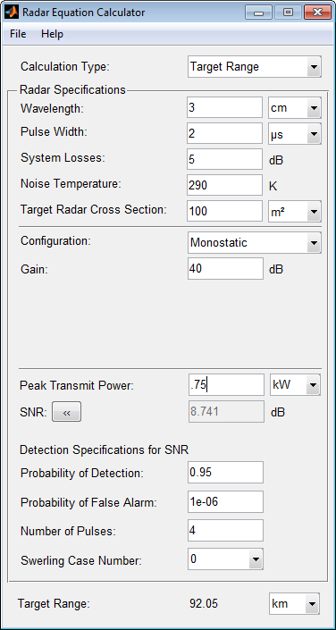
The maximum detection range is approximately the same as in the previous example, but the transmitted power is reduced by 25%.

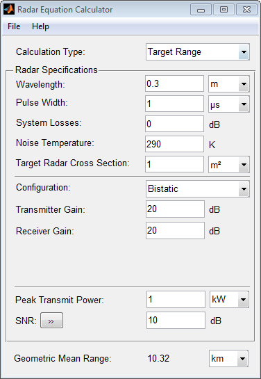
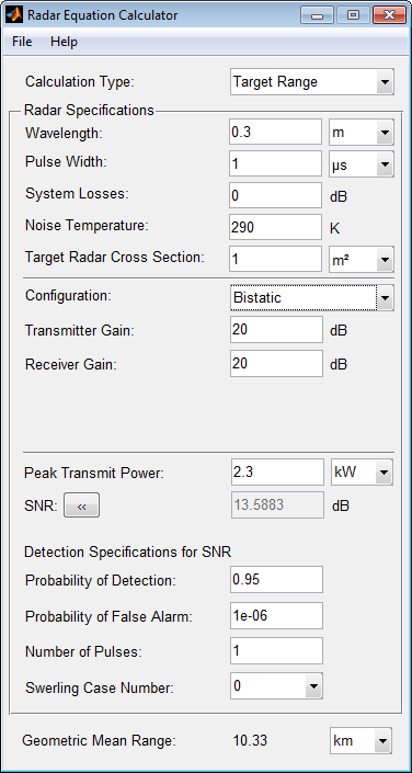
This example shows how to solve for the geometric mean range of a target for a bistatic radar system.

Specify the Calculation Type as Target Range.

Specify the Configuration as bistatic.

Provide a Transmitter Gain and a Receiver Gain parameter, instead of the single gain needed in the monostatic case.

Alternatively, to achieve a particular probability of detection and probability of false alarm, open the Detection Specifications for SNR menu.

Enter values for Probability of Detection and Probability of False Alarm, Number of Pulses, and Swerling Case Number.

This example shows how to compute the required peak transmit power of a 10 GHz, bistatic X-band radar for a 80 km total bistatic range, and 10 dB received SNR.

The system has a 40 dB transmitter gain and a 20 dB receiver gain. The required receiver SNR is 10 dB.

From the Calculation Type drop-down list, choose Peak Transmit Power as the solution type.

Choose Configuration as bistatic.

From the system specifications, set Transmitter Gain to 40 dB and Receiver Gain to 20 dB.

Set the SNR detection threshold to 10 dB and the Wavelength to 0.3 m.

Assume the target is a fighter aircraft having a Target Radar Cross Section value of 2 m2.

Choose Range from Transmitter as 50 km, and Range from Receiver as 30 km.

Set the Pulse Width to 2 µs and the System Losses to 0 dB.

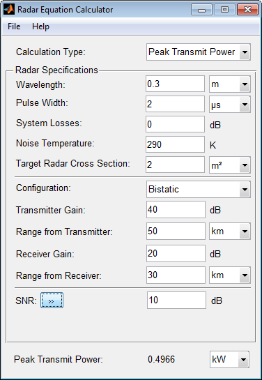
The required Peak Transmit Power is about 0.5 kW.

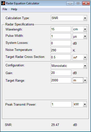
This example shows how to compute the received SNR for a monostatic radar with 1 kW peak transmit power with a target at a range of 2 km.

Assume a 2 GHz radar frequency and 20 dB antenna gain.

From the Calculation Type drop-down list, choose SNR as the solution type and set the Configuration as monostatic.

Set the Gain to 20, the Peak Transmit Power to 1 kW, and the Target Range to 2000 m.

Set the Wavelength to 15 cm.

Find the received SNR of a small boat having a Target Radar Cross Section value of 0.5 m2.

The Pulse Width is 1 µs and System Losses are 0 dB.

Related Examples

Parameters

expand all

Target Range – solves for maximum target range based on transmit power of the radar and desired received SNR.

Peak Transmit – Power computes power needed to transmit based on known target range and desired received SNR.

SNR – calculates the received SNR value based on known range and transmit power.

Specify the wavelength of radar operating frequency in m, cm, or mm.

The wavelength is the ratio of the wave propagation speed to frequency. For electromagnetic waves, the speed of propagation is the speed of light.

Denoting the speed of light by c and the frequency (in hertz) of the wave by f, the equation for wavelength is λ = c/f.

Specify the single pulse duration in µs, ms, or s.

System Losses represents a general loss factor that comprises losses incurred in the system components and in the propagation to and from the target.

The system noise temperature is the product of the system temperature and the noise figure.

Specify the target radar cross section in , or dBsm.

The target radar cross section is nonfluctuating.

Monostatic – Transmitter and receiver are co-located (monostatic radar).

Bistatic – Transmitter and receiver are not co-located (bistatic radar).

When the transmitter and receiver are co-located (monostatic radar), the transmit and receive gains are equal.

This parameter is enabled only if the Configuration is set to Monostatic.

Specify the transmitter peak power in kW, mW, W, or dBW.

This parameter is enabled only if the Calculation Type is set to Target Range or SNR.

Specify an SNR value, or calculate an SNR value using Detection Specifications for SNR.

You can calculate the SNR required to achieve a particular probability of detection and probability of false alarm using Shnidman's equation. To calculate the SNR value:

  1. Click the arrows to the right of the SNR label to open the Detection Specifications for SNR menu.

  2. Enter values for Probability of Detection, Probability of False Alarm, Number of Pulses, and Swerling Case Number.

This parameter is enabled only if the Calculation Type is set to Target Range or Peak Transmit Power.

Specify the detection probability used to estimate SNR using Shnidman's equation.

This parameter is enabled only when the Calculation Type is set to Peak Transmit Power or Target Range, and you select the Detection Specifications for SNR button for the SNR parameter.

Specify the false-alarm probability used to estimate SNR using Shnidman's equation.

This parameter is enabled only when the Calculation Type is set to Peak Transmit Power or Target Range, and you select the Detection Specifications for SNR button for the SNR parameter.

Specify a single pulse, or the number of pulses used for noncoherent integration in Shnidman's equation.

Use multiple pulses to reduce the transmitted power while maintaining the same maximum target range.

This parameter is enabled only when the Calculation Type is set to Peak Transmit Power or Target Range, and you select the Detection Specifications for SNR button for the SNR parameter.

Specify the Swerling case number used to estimate SNR using Shnidman's equation:

  • 0 – Nonfluctuating pulses.

  • 1 – Scan-to-scan decorrelation. Rayleigh/exponential PDF–A number of randomly distributed scatterers with no dominant scatterer.

  • 2 – Pulse-to-pulse decorrelation. Rayleigh/exponential PDF– A number of randomly distributed scatterers with no dominant scatterer.

  • 3 – Scan-to-scan decorrelation. Chi-square PDF with 4 degrees of freedom. A number of scatterers with one dominant.

  • 4 – Pulse-to-pulse decorrelation. Chi-square PDF with 4 degrees of freedom. A number of scatterers with one dominant.

Swerling case numbers characterize the detection problem for fluctuating pulses in terms of:

  • A decorrelation model for the received pulses.

  • The distribution of scatterers affecting the probability density function (PDF) of the target radar cross section (RCS).

The Swerling case numbers consider all combinations of two decorrelation models (scan-to-scan; pulse-to-pulse) and two RCS PDFs (based on the presence or absence of a dominant scatterer).

This parameter is enabled only when the Calculation Type is set to Peak Transmit Power or Target Range, and you select the Detection Specifications for SNR button for the SNR parameter.

Specify target range in m, km, mi, or nmi.

This parameter is enabled only when the Calculation Type is set to Peak Transmit Power or SNR, and the Configuration is set to Monostatic.

When the transmitter and receiver are not co-located (bistatic radar), specify the transmitter gain separately from the receiver gain.

This parameter is enabled only if the Configuration is set to Bistatic.

When the transmitter and receiver are not co-located (bistatic radar), specify the transmitter range separately from the receiver range.

You can specify range in m, km, mi, or nmi.

This parameter is enabled only when the Calculation Type is set to Peak Transmit Power or SNR, and the Configuration is set to Bistatic.

When the transmitter and receiver are not co-located (bistatic radar), specify the receiver gain separately from the transmitter gain.

This parameter is enabled only if the Configuration is set to Bistatic.

When the transmitter and receiver are not co-located (bistatic radar), specify the receiver range separately from the transmitter range.

You can specify range in m, km, mi, or nmi.

This parameter is enabled only when the Calculation Type is set to Peak Transmit Power or SNR, and the Configuration is set to Bistatic.

Version History

Introduced in R2021a