SDA Optical Communication Terminal Waveform Generation
This example shows how to generate over-the-air (OTA) frames for free space optical communications (FSOC), as defined by the Space Development Agency (SDA) Optical Communications Terminal (OCT) standard version 4.0.0 [1]. This standard enables optical communication terminals to inter-operate when at least one endpoint is space-based. This example explains the functions of the synchronization and channel coding layer and the physical layer.
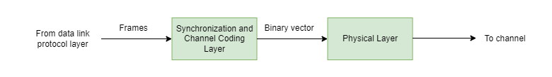
This figure shows the synchronization and channel coding layer and the physical layer at the transmitting end. The synchronization and channel coding layer receives input frames, performs synchronization and channel coding functions, and sends a binary vector to the physical layer. The physical layer then processes the binary vector to generate modulated samples using on-off keying non-return-to-zero (OOK-NRZ), Manchester, or Manchester burst-modes Manchester-BM12, or Manchester-BM16.
Synchronization and Channel Coding Layer
This figure shows the functional blocks for the generation of OTA frames.
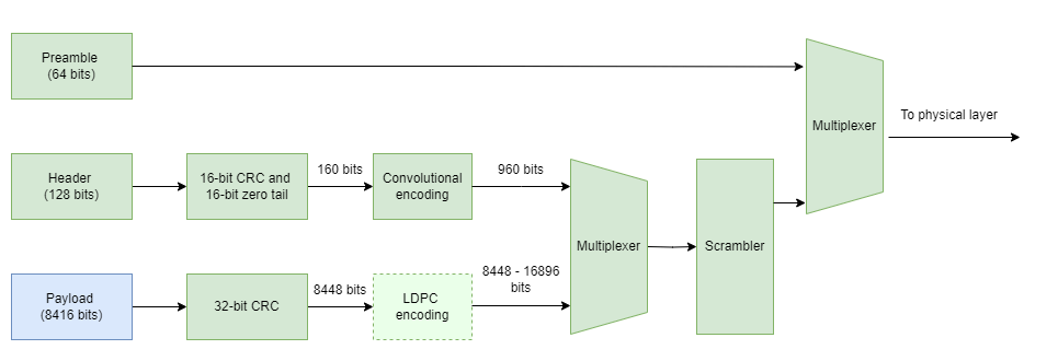
To generate OTA frames, follow these steps:
Generate Frames — All modem frames, whether data, idle, or management, carry a fixed payload size of 8416 bits. Obtain this payload data from the datalink protocol sublayer.
Preamble Addition — Each OCT frame starts with a preamble sequence, used by the receiver for frame synchronization. Use the 64-bit preamble 0x53225B1D0D73DF03 (MSB-first) for all OCT modem frames.
Header Creation — Generate a 128-bit header sequence for each frame, followed by a 16-bit cyclic redundancy check (CRC), and add 16 tail bits to terminate the convolutional encoder. Perform forward error correction (FEC) encoding using a non-systematic convolutional code with constraint length 7 and rate 1/6.
Payload Encoding — Calculate a 32-bit CRC for the payload, and then encode it using the quasi-cyclic low-density parity check (QC-LDPC) code derived from [2]. The number of parity bits varies based on the code rate, ranging from 0 bits (uncoded) to up to 9216 bits (at an LDPC code rate 1/2).
Frame Assembly — Attach the LDPC-encoded payload information bits to the convolutionally encoded header bits, and then scramble the resulting sequence. Add the 64-bit preamble sequence to the scrambled sequence to generate the complete OTA frame.
Set Configuration Parameters
Generate two data payload frames.
frameLen = 8416;
numDataFrames = 2;
rng("default")
data = randi([0 1],frameLen,numDataFrames);
Create a default SDA OCT System object™ using HelperSDAOCTWaveformGenerator. Set the FrameType property to "data" or "management" to generate waveforms corresponding to data frames or management frames.
SDAOCTObj = HelperSDAOCTWaveformGenerator;
SDAOCTObj.FrameType = "data";
SDA OCT waveform generation supports the automatic repeat request (ARQ) approach, which ensures reliable frame delivery through acknowledgments. You can enable ARQ by setting ARQMaxRetransmissions to a value greater than zero. For high SNR inter-satellite links, you can disable ARQ by setting ARQMaxRetransmissions to zero. When ARQ is enabled, the OCT transmits an acknowledgment (ACK) for successfully received data and management frames and retransmits any frames for which it does not explicitly receive an ACK, up to the ARQMaxRetransmissions limit. Successful reception of a frame requires passing the payload CRC-32. Receivers consider frames lacking an explicit ACK as negatively acknowledged (NAK). The ARQ configuration parameters, ARQMaxRetransmissions and ARQHoldOffSpan, remain fixed throughout a session and thus are nontunable properties. Each ARQ cycle effectively consists of ARQHoldOffSpan*16 frames. To determine the transmission time for an ARQ cycle, multiply the effective number of frames by the frame duration at the configured baud rate. The ACK/NAK deadline for a previously transmitted FSO frame corresponds to the transmission time of one ARQ cycle.
SDAOCTObj.ARQMaxRetransmissions =4; % Range:[0, 5] SDAOCTObj.ARQHoldOffSpan = 3; % Range:[0, 256]
Enabling ARQ enables all the acknowledgment-related properties of the System object. Specify the transmission attempt number using RetransmissionCount. When HasAck is true, the current frame carries acknowledgment information, and AckStatus applies to the FSO frame with sequence number AckStartSequenceNum and up to consecutive FSO frames. When HasAck is false, the current frame does not have acknowledgment information, and the object ignores AckStatus. If the transmitter does not receive an ACK for a transmitted frame, it schedules a retransmission in the next ARQ cycle until the retry limit ARQMaxRetransmissions is reached.
For each of these properties, if you specify as a scalar, the same value applies to all input frames. To configure different values for a property for each frame in multiframe input, specify the property as a vector whose length matches the number of input frames.
% Acknowledge that the frames with frame sequence numbers 14 to 17 are % received and 21 to 24 are not received. SDAOCTObj.RetransmissionCount =0; % Range:[0, ARQMaxRetransmissions] SDAOCTObj.HasAck =
true; % true|false SDAOCTObj.AckStatus = [true; false]; SDAOCTObj.AckStartSequenceNum = [14 21]; SDAOCTObj.AckSpan =
2; % Range:[0, 5]
To support external ranging and time transfer calculations, the OCT provides frame timestamps for all frame types, indicating the egress time from the transmit aperture plane. TODEpoch and PicoSecInTODEpoch represent the timestamp, where TODEpoch captures the number of seconds in the time-of-day epoch and PicoSecInTODEpoch captures the number of picoseconds within the current second. TODEpochFrameOffset specifies if the timestamp applies to the current frame (0) or preceding frames (1–7).
For each of these properties, if you specify as a scalar, the same value applies to all input frames. To configure different values for a property for each frame in multiframe input, specify the property as a vector whose length matches the number of input frames.
SDAOCTObj.TODEpoch = 5; % Range:[0, 59] SDAOCTObj.PicoSecInTODEpoch = [1.4e6, 1.9e9]; % Range:[0, 999999999999] SDAOCTObj.TODEpochFrameOffset =0; % Range:[0, 7]
Use FCCHOpcode and FCCHPayload to provide embedded fast control channel (FCCH) messages. The FCCH is a low-rate channel with dedicated bandwidth for the robust, low-latency transport of short messages between OCTs. Positioned in the frame header, the FCCH benefits from both error detection through the header CRC and error correction through the header FEC. The FCCH does not support ARQ.
• FCCHOpcode (6 bits) — Determines the format of the FCCH payload. Table 3-13 [1] lists FCCHOpcode values for various FCCH types.
• FCCHPayload (16 bits) — Payload bits, defined for each FCCH type in Section 3.4.6.2 Table 3-14 [1].
When no FCCH data awaits transport, specify the FCCHOpcode as [1 1 1 1 1 1], and set all FCCH payload bits to ones.
% Consider LAPC_BLER_REPORT FCCH Type and transmit number of payload CRC errors in FCCHPayload
SDAOCTObj.FCCHOpcode = [0 0 0 0 0 0]';             % LAPC_BLER_REPORT
SDAOCTObj.FCCHPayload =  [zeros(16,1) ones(16,1)]; % Number of payload CRC errors
The OCT supports both OOK-NRZ and Manchester modulation formats. Additionally, Manchester modulation includes two burst-mode options: Manchester-BM12, which operates with a 1/12 duty cycle, and Manchester-BM16, which operates with a 1/16 duty cycle. In OOK-NRZ encoding, the presence of a laser corresponds to a 1, and the absence of a laser corresponds to a 0. In Manchester encoding, a transition from symbol 1 to symbol 0 represents bit 1, while a transition from symbol 0 to symbol 1 represents bit 0, where symbol 1 denotes the presence of a laser and symbol 0 denotes its absence.
Burst-mode Manchester encoding provides higher peak power at lower data rates, making it ideal for long-range applications. In burst mode, data is transmitted in bursts along with an initial training sequence to facilitate clock and data recovery. Each burst includes 128 bits transmitted in 102.4 ns, with burst intervals of 1.23 µs for Manchester-BM12 and 1.64 µs for Manchester-BM16.
SDAOCTObj.ModulationFormat ="Manchester-BM12"; % OOK-NRZ|Manchester|Manchester-BM12|Manchester-BM16 SDAOCTObj.AMFrequency =
50e3; % 40e3|50e3 in Hz
SDA waveform generation supports a hybrid FEC approach, enabling or disabling FEC based on system and environmental conditions. To enable FEC, set the LDPCRateID to a value greater than zero. If you specify LDPCRateID as a scalar, the same value applies to all input frames. To configure different values for each frame in a multiframe input, specify this property as a vector whose length matches the number of input frames. Manchester-BM12 and Manchester-BM16 use an LDPCRateID of 4, which corresponds to an LDPC code rate of "1/2".
In Manchester-BM12 and Manchester-BM16 modulation schemes, the ModulationIndex is internally set to 0.33. In Manchester and OOK-NRZ, valid ModulationIndex values come from the set {0, 0.1, 0.2, 0.33} and the range [0.8, 1]. When ModulationIndex is greater than zero, the encoded data undergo amplitude modulation with a tracking tone based on the specified ModulationIndex. The tracking tone is implemented as a sinusoidal signal with a frequency of either 40 kHz or 50 kHz.
This table outlines the supported signaling rates for various modulation formats.
Modulation Format | Optical Signaling Rate (MHz) |
OOK-NRZ | 2500, 1250, 625, 312.5 |
Manchester | 2500, 1250, 625, 312.5 |
Manchester-BM12 | 2500 |
Manchester-BM16 | 2500 |
% For "Manchester" or "OOK-NRZ" modulation, LDPCRateID can range from 0 to % 4. For "Manchester-BM12" or "Manchester-BM16" modulation, LDPCRateID of 4 % and SignalingRate of 2500MHz is considered internally. if strcmp(SDAOCTObj.ModulationFormat,"OOK-NRZ") || strcmp(SDAOCTObj.ModulationFormat,"Manchester") SDAOCTObj.LDPCRateID = 4; % Range:[0 4] SDAOCTObj.SignalingRate =1250e6; % 2500|1250|625|312.5 in MHz SDAOCTObj.ModulationIndex = 0.8; % 0.1|0.2|0.33 or Range:[0.8, 1] end % Set peak power to update the maximum power of the modulated data SDAOCTObj.PeakPower = 24;
Generate Waveform
Generate the SDA OCT waveform for the payload data by passing the frame sequence number and the data bits as a column vector to the HelperSDAOCTWaveformGenerator System object.
frameSequenceNum = 1;
SDADataWaveform = SDAOCTObj(frameSequenceNum,data(:));
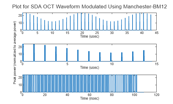
Plot the waveform at various time scales to understand the timing and impact of duty cycle and amplitude modulation (AM) tone frequency on burst modulation.
samplesPerSlot = 10;
samples = repelem(SDADataWaveform,samplesPerSlot);
tsamp = 1/(samplesPerSlot*SDAOCTObj.SignalingRate);
t = 0:tsamp:tsamp*(length(samples)-1);

tl = tiledlayout(3,1);
ax(1) = nexttile;
samplesToPlot = floor(length(samples)/10);
plot(t(1:samplesToPlot)*1e6,samples(1:samplesToPlot))

ax(2) = nexttile;
samplesToPlot = floor(length(samples)/30);
plot(t(1:samplesToPlot)*1e6,samples(1:samplesToPlot))

ax(3) = nexttile;
samplesToPlot = floor(length(samples)/4e3);
plot(t(1:samplesToPlot)*1e9,samples(1:samplesToPlot))

xlabel(ax(1:2),"Time (\musec)")
xlabel(ax(3),"Time (nsec)")
ylabel(ax,"Peak power","FontSize",8)
title(tl,"Plot for SDA OCT Waveform Modulated Using " + SDAOCTObj.ModulationFormat)
Idle Frames
During nominal operation, OCT modem transmits frames without gaps between adjacent frames. If no data is available for transmission, the modem inserts consecutive idle frames into the transmitted stream until other types of traffic frames become available. To generate waveforms for idle frames, set the FrameType to idle. Since ARQ is disabled for idle frames, provide the frame sequence number and the number of idle frames to the System object to generate the waveforms.
% Generate number of idle frames equal to the number of data frames
numIdleFrames = numDataFrames;
% Update the frame sequence number
frameSequenceNum = frameSequenceNum+numDataFrames;
% Update the parameters for idle frames
SDAOCTObj.FrameType = "idle";
SDAOCTObj.TODEpoch = 2;
SDAOCTObj.PicoSecInTODEpoch = 1:1e3:numIdleFrames*1e3;
SDAOCTObj.TODEpochFrameOffset = 0;
% Generate the waveform for idle frames
SDAIdleWaveform = SDAOCTObj(frameSequenceNum,numIdleFrames);
Supporting Files
This example uses these helper files:
HelperSDAOCTWaveformGenerator— Generate SDA OCT waveformHelperSDAOCTLDPCEncode— Perform SDA OCT LDPC encodingHelperSDAOCTModulator— Perform SDA OCT modulation
References
[1] Space Development Agency. Optical Communications Terminal Standard Version 4.0.0. SDA, June 28, 2024.
[2] The 3rd Generation Partnership Project. NR; Multiplexing and Channel Coding. TS 38.212. 3GPP, July 2018.