ModuleAssembly
Description
Use ModuleAssembly to create a module assembly object that
represents a number of Module objects
connected electrically in series or in parallel. You can use this object as an input to the
Pack object to
create larger battery models.
To generate a Simscape™ model of your ModuleAssembly object, use the buildBattery
function.
The ModuleAssembly object only supports the definition of structural or
design parameters. You can modify the run-time parameters for this object and its constituent
module models after you create the model. The ModuleAssembly object keeps
track of its unique constituent module models and generates parameters for these models
instead of doing it for every model instance. You can generate a script that contains all the
parameters of the ModuleAssembly object by specifying the
MaskParameters argument in the buildBattery
function. A unique module model is characterized by having the same properties (such as
NumSeriesAssemblies and ModelResolution) and the
same constituent cell properties (such as name, format, and weight).
The ModuleAssembly object is the fourth element stage of a battery pack
system model in a bottom-up approach. Pack models are required for architecture evaluation in
early development stages, software and hardware development, system integration and
requirement evaluation, cooling system design, control strategy development
hardware-in-the-loop, and many more applications.

To specify the number and attributes of the modules, use the Module
property.
This figure shows a module assembly that comprises two modules made of four parallel assemblies of 48 parallel cylindrical cells each.

Thermal Boundary Conditions
Thermal boundary conditions define the specific heat transfer mechanisms that occur at each interface of a cell thermal model and its surroundings. In battery systems, cells are typically thermally coupled to different heat sources and sinks, all of which have an effect on the battery cell temperature. The number and type of thermal boundary conditions for a cell model depends on the thermal and mechanical design of the battery system.
For example, you can place cells on an aluminium cooling plate to enhance heat removal and, at the same time, join them together mechanically with a potting compound that effectively eliminates or decreases the inter-cell heat exchange path. The cell temperature has a direct impact on battery performance and lifetime. Therefore, it is crucial to predict this state in dynamic simulation.
Inside a battery object, you can set up a thermal network of lumped-thermal-mass cell models to simultaneously capture the thermal paths to the ambient, the coolant, and/or the cooling plate:

These options are not mutually exclusive. For example, your battery model can combine both the coolant thermal path and the cooling thermal plates to model individual thermal resistances between the individual cells and the sections of the cooling plate.
For more information about thermal paths, see the AmbientThermalPath, CoolantThermalPath, and CoolingPlate properties.
You can also model direct cell-to-cell heat exchange. This is important when you want to simulate more detailed thermal management strategies or even thermal propagation scenarios where inter-cell heat transfer happens at faster rates than ambient or coolant rates. In the battery industry, you can link battery cells to each other through many different means. For example, you can link cylindrical cells by using potting compounds for mechanical rigidity, stability, and thermal isolation, or other types of thermal interface materials. You can also use dielectric fluids or other compounds to heat or cool down cylindrical cells, as well as forced air convection.
You can define the thermal parameters for the inter-cell heat exchange after you create the battery model. You can find these parameters from first principles calculations and more detailed 3D simulations.

These options are not mutually exclusive.
For more information about inter-cell thermal paths, see the InterCellThermalPath and InterCellRadiativeThermalPath properties.
Creation
Description
Note
To quickly create a ModuleAssembly
object, use the batteryModuleAssembly function. By using this function, you avoid importing
the namespace, using the full class name, or dealing only with name-value arguments when
creating the object. (since R2024a)
To create a ModuleAssembly object without using
the batteryModuleAssembly function, at the MATLAB® Command Window, you must run this command at least once each MATLAB session:
import simscape.battery.builder.*;
batteryModuleAssembly = ModuleAssembly
batteryModuleAssembly = ModuleAssembly(Name=Value)
batteryModuleAssembly = ModuleAssembly(...
    Module=repmat(Module,1,2), ...
    StackingAxis="Y",...
    InterModuleGap=simscape.Value(0.005,"m"));
You can define the number and types of modules in the Module
property. If your module assembly comprises many modules with the same property values,
you can use the repmat function to specify the Module property.
Otherwise, specify an array of distinct modules.
Properties
Set of battery modules in the module assembly, specified as a Module object or an array of Module objects. The ModuleAssembly object electrically connects the modules in series or in parallel according to the CircuitConnection property. If your module assembly comprises many modules with exactly the same property values, you can use the repmat function to specify this property. Otherwise, specify an array of distinct modules.
Note
The array dimensions of the Module input (rows:columns) do not affect how the ModuleAssembly object stacks the modules. Only the StackingAxis and NumLevels properties influence the stacking strategy.
Shortest distance between modules inside the module assembly, specified as a positive scalar or a simscape.Value object that represents a positive scalar with a unit of length. The value of this property must be less than 0.1 m.
If you set this property directly with a positive scalar value instead of using a simscape.Value object, this object converts the value to a simscape.Value object with meter as its physical unit.
Type of electrical connection between modules, specified as either "Series or "Parallel".
Number of levels, tiers, or floors of the module assembly, specified as a positive integer. The value of this property must be equal to or less than the number of modules in the module assembly.
The ModuleAssembly object stacks the modules symmetrically according to the number of levels and modules in the assembly.
For example, this figure shows how the ModuleAssembly object stacks four identical modules when you set this property to 2.

This figure shows how the ModuleAssembly object stacks five identical modules when you still set this property to 2.

This figure shows how the ModuleAssembly object stacks five identical modules when you set this property to 3 instead.

State-of-charge balancing strategy for the module assembly, specified as
"None", "Passive", or
"External".
Set this property to "Passive" to add an ideal balancing
circuit connected in parallel to every parallel assembly inside the
ModuleAssembly Simscape model and a physical port of size equal to
NumSeriesAssemblies*numel(Module) for switch control.
To specify and model an external cell balancing strategy, set this property to
"External". The ModuleAssembly
(Generated Block) then exposes two electrical array-of-nodes ports,
+BUS and -BUS. For desktop simulations and
hardware-in-the-loop battery emulation hardware, use this option in conjunction with the
Passive Balancing
Interface block.
Note
Setting this property automatically propagates its value to all the subcomponent battery
objects inside this ModuleAssembly object. However, this change does not
propagate to the other battery objects in your MATLAB workspace. If you do not set this
property when you create this ModuleAssembly object, then the default value is
automatically propagated to all its subcomponent battery objects.
Example:
batteryModuleAssembly.BalancingStrategy = "Passive"
Option to use a simple thermal resistance block connected between the cells and a
Simscape thermal network, specified as
"CellBasedThermalResistance" or
"None".
Note
Setting this property automatically propagates its value to all the subcomponent battery
objects inside this ModuleAssembly object. However, this change does not
propagate to the other battery objects in your MATLAB workspace. If you do not set this
property when you create this ModuleAssembly object, then the default value is
automatically propagated to all its subcomponent battery objects.
Example: batteryModuleAssembly.AmbientThermalPath =
"CellBasedThermalResistance"
Option to use a simple thermal resistance block connected between the cells and a
Simscape thermal network, specified as
"CellBasedThermalResistance" or
"None". If you use a cooling plate, the object connects the
thermal resistance block between the cells and the cooling plate block by using an array
of thermal nodes.
Note
Setting this property automatically propagates its value to all the subcomponent battery
objects inside this ModuleAssembly object. However, this change does not
propagate to the other battery objects in your MATLAB workspace. If you do not set this
property when you create this ModuleAssembly object, then the default value is
automatically propagated to all its subcomponent battery objects.
Example:
batteryModuleAssembly.CoolantThermalPath =
              "CellBasedThermalResistance"
Since R2023a
Option to use a cooling plate component at a specific surface boundary, specified as
"Top", "Bottom", or
"None".
If you want the Battery Pack Builder to automatically add a cooling plate in your
generated model, specify the path of the Cooling Plate block by using the
CoolingPlateBlockPath property.
Note
Setting this property automatically propagates its value to all the subcomponent battery
objects inside this ModuleAssembly object. However, this change does not
propagate to the other battery objects in your MATLAB workspace. If you do not set this
property when you create this ModuleAssembly object, then the default value is
automatically propagated to all its subcomponent battery objects.
Example:
batteryModule.CoolingPlate = "Top"
Since R2023a
Option to specify which cooling plate block you want to assign to the ModuleAssembly
object at the boundary defined by the CoolingPlate property,
specified as "batt_lib/Thermal/Edge Cooling",
"batt_lib/Thermal/Parallel Channels",
""batt_lib/Thermal/U-Shaped Channels"", or
"None".
This figure shows the internal structure of a module assembly when you set the
CoolingPlate property to "Bottom":

Note
Setting this property automatically propagates its value to all the subcomponent battery
objects inside this ModuleAssembly object. However, this change does not
propagate to the other battery objects in your MATLAB workspace. If you do not set this
property when you create this ModuleAssembly object, then the default value is
automatically propagated to all its subcomponent battery objects.
Example:
batteryModuleAssembly.CoolingPlateBlockPath = "batt_lib/Thermal/Edge
              Cooling"
Preferential stacking direction for the arrangement of battery cells in a 2-D
Cartesian coordinate system, specified as "X" or
"Y".
This figure shows the global coordinate system for batteries.

To plot the module assembly object in the direction of the
x-axis, set this property to "X" before
creating the BatteryChart object.
Example: batteryModuleAssembly.StackingAxis = "Y"
Additional non-cell-related mass added to the module assembly by components such as busbars, tabs, and collector plates, specified as a strictly positive double greater than or equal to 1.
Example:
batteryModuleAssembly.MassFactor = 1.2
Location of the battery object in a 3-D Cartesian coordinate system, specified as a vector of real and finite entries.
Example: batteryModuleAssembly.Position = [0 0 0]
Name of the battery module assembly, specified as a string.
Example: batteryModuleAssembly.Name = "ModuleAssembly2"
Option to use electrical resistance blocks to represent additional electrical
resistances from non-cell components, specified as 'off',
'on', or as numeric or logical 1
(true) or 0 (false). A
value of 'on' is equivalent to true, and
'off' is equivalent to false. Thus,
you can use the value of this property as a logical value. The value is stored as an
on/off logical value of type matlab.lang.OnOffSwitchState.
Example:
batteryModuleAssembly.NonCellResistance = 'on'
Since R2023a
Option to use thermal resistance blocks to represent a linear cell-to-cell heat
transfer path between adjacent battery cells, specified as
'off', 'on', or as numeric or
logical 1 (true) or 0
(false). A value of 'on' is equivalent
to true, and 'off' is equivalent to
false. Thus, you can use the value of this property as a logical
value. The value is stored as an on/off logical value of type
matlab.lang.OnOffSwitchState.
Enabling the inter-cell thermal path is useful only when you have selected a cell thermal model and more than one cell or cell model exists inside the battery.
You can define the value for the thermal resistance parameter after model creation.

If you set this property to 'on', you cannot set the
InterCellRadiativeThermalPath property to
'on'.
For more information about modeling inter-cell thermal exchange, see Model Heat Exchange Between Cells.
Note
Setting this property automatically propagates its value to all the subcomponent battery
objects inside this ModuleAssembly object. However, this change does not
propagate to the other battery objects in your MATLAB workspace. If you do not set this
property when you create this ModuleAssembly object, then the default value is
automatically propagated to all its subcomponent battery objects.
Example: batteryModuleAssembly.InterCellThermalPath = "on"
Since R2023a
Option to use thermal resistance blocks to represent a radiative cell-to-cell heat
transfer path between adjacent battery cells, specified as
'off', 'on', or as numeric or
logical 1 (true) or 0
(false). A value of 'on' is equivalent
to true, and 'off' is equivalent to
false. Thus, you can use the value of this property as a logical
value. The value is stored as an on/off logical value of type
matlab.lang.OnOffSwitchState.
Enabling the inter-cell radiative thermal path is useful only when you have selected a cell thermal model and more than one cell or cell model exists inside the battery.
You can define the value for the radiation heat transfer parameters after model creation.

If you set this property to 'on', you cannot set the
InterCellThermalPath property to
'on'.
For more information about modeling inter-cell thermal exchange, see Model Heat Exchange Between Cells.
Note
Setting this property automatically propagates its value to all the subcomponent battery
objects inside this ModuleAssembly object. However, this change does not
propagate to the other battery objects in your MATLAB workspace. If you do not set this
property when you create this ModuleAssembly object, then the default value is
automatically propagated to all its subcomponent battery objects.
Example: batteryModuleAssembly.InterCellRadiativeThermalPath =
"on"
This property is read-only.
Volume of the battery, returned as a simscape.Value object with a unit of volume.
This property is read-only.
Cumulative mass of the battery, returned as a simscape.Value object with a unit of mass.
Since R2023a
This property is read-only.
Cumulative cell capacity of the battery, returned as a simscape.Value object with unit of current multiplied by time.
The value of this property is equal to the individual cell capacity multiplied by the number of cells electrically connected in parallel inside this battery object.
Since R2023a
This property is read-only.
Cumulative cell energy of the battery, returned as a simscape.Value object with unit of energy.
The value of this property is equal to the individual cell energy multiplied by the total number of cells inside this battery object.
This property is read-only.
Number of cell model blocks in simulation, returned as a double.
This property is read-only.
Numbering for all of the cells inside of the battery, returned as a structure.
This property is read-only.
Vectorized thermal node information for external boundary conditions, returned as a structure. This information comprise XY location, XY dimensions, and number of thermal nodes.
This property is read-only.
Type of battery, returned as "ModuleAssembly".
Examples
Create a Cell object with a pouch geometry.
batteryCell = Cell(Geometry=PouchGeometry)
Create a ParallelAssembly object of three parallel cells with the
default topology.
pSet = ParallelAssembly(Cell=batteryCell,NumParallelCells=3)
Use this ParallelAssembly object to create a
Module object of 10 parallel assemblies connected in series.
batteryModule = Module(ParallelAssembly=pSet,NumSeriesAssemblies=10)
Use this batteryModule object to create a
ModuleAssembly object of four identical modules connected in
series.
batteryModuleAssembly = ModuleAssembly(Module=repmat(batteryModule,1,4))
Visualize the module assembly by using a BatteryChart
object.
moduleAssemblyChart = BatteryChart(Battery=batteryModuleAssembly);
Create a Cell object with a Cylindrical geometry and enable the
modeling of its thermal effects.
battCell = Cell(Geometry = CylindricalGeometry);
battCell.CellModelOptions.BlockParameters.thermal_port = "model";
Create a ParallelAssembly object of 30 parallel cells in five rows
with the default topology.
pSet = ParallelAssembly(Cell=battCell, NumParallelCells = 30, Rows = 5);
Use this ParallelAssembly object to create a
Module object of two parallel assemblies connected in series.
module = Module(ParallelAssembly=pSet, NumSeriesAssemblies = 2);
Use this Module object to create a ModuleAssembly
object of six identical modules connected in series.
moduleAssembly = ModuleAssembly(Module = repmat(module,1,6));
Assign a single cooling plate to the bottom of the module assembly and choose the Parallel Channels block as the cooling plate block.
moduleAssembly.CoolingPlate = "Bottom";
moduleAssembly.CoolingPlateBlockPath = "batt_lib/Thermal/Parallel Channels";
Build this ModuleAssembly object by calling the
buildBattery
function.
buildBattery(moduleAssembly, "LibraryName","Permutation1_SingleBottomCoolingPlate",...
"MaskParameters","VariableNamesByType","MaskInitialTargets","VariableNamesByInstance");
This figure shows the internal structure of the ModuleAssembly object:
Create a Cell object with a Cylindrical geometry and enable the
modeling of its thermal effects.
battCell = Cell(Geometry = CylindricalGeometry);
battCell.CellModelOptions.BlockParameters.thermal_port = "model";
Create a ParallelAssembly object of 30 parallel cells in five rows
with the default topology.
pSet = ParallelAssembly(Cell=battCell, NumParallelCells = 30, Rows = 5);
Use this ParallelAssembly object to create a
Module object of two parallel assemblies connected in series.
module = Module(ParallelAssembly=pSet, NumSeriesAssemblies = 2);
Use this Module object to create a ModuleAssembly
object of six identical modules connected in series.
moduleAssembly = ModuleAssembly(Module = repmat(module,1,6));
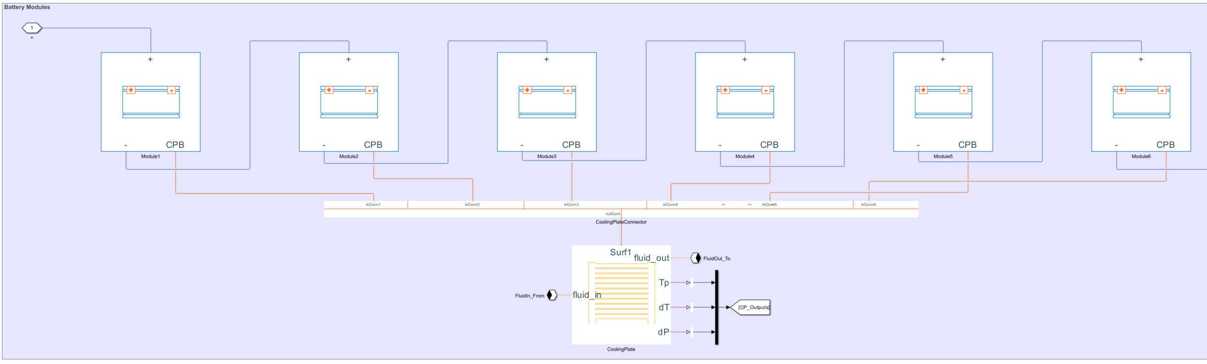
Assign a cooling plate to the bottom of the first, third, and fifth modules inside the module assembly and choose the Parallel Channels block as the cooling plate block.
moduleAssembly.Module(1).CoolingPlate = "Bottom";
moduleAssembly.Module(1).CoolingPlateBlockPath = "batt_lib/Thermal/Parallel Channels";
moduleAssembly.Module(3).CoolingPlate = "Bottom";
moduleAssembly.Module(3).CoolingPlateBlockPath = "batt_lib/Thermal/Parallel Channels";
moduleAssembly.Module(5).CoolingPlate = "Bottom";
moduleAssembly.Module(5).CoolingPlateBlockPath = "batt_lib/Thermal/Parallel Channels";
Build this ModuleAssembly object by calling the
buildBattery
function.
buildBattery(moduleAssembly, "LibraryName","Permutation2_ModuleSpecificBottomCoolingPlate",...
"MaskParameters","VariableNamesByType","MaskInitialTargets","VariableNamesByInstance");
This figure shows the internal structure of the ModuleAssembly object:

Create a Cell object with a Cylindrical geometry and enable the
modeling of its thermal effects.
battCell = Cell(Geometry = CylindricalGeometry);
battCell.CellModelOptions.BlockParameters.thermal_port = "model";
Create a ParallelAssembly object of 30 parallel cells in five rows
with the default topology.
pSet = ParallelAssembly(Cell=battCell, NumParallelCells = 30, Rows = 5);
Use this ParallelAssembly object to create a
Module object of two parallel assemblies connected in series.
module = Module(ParallelAssembly=pSet, NumSeriesAssemblies = 2);
Use this Module object to create a ModuleAssembly
object of six identical modules connected in series.
moduleAssembly = ModuleAssembly(Module = repmat(module,1,6));
Assign a single cooling plate to the top of the module assembly and choose the Parallel Channels block as the cooling plate block.
moduleAssembly.CoolingPlate = "Top";
moduleAssembly.CoolingPlateBlockPath = "batt_lib/Thermal/Parallel Channels";
Build this ModuleAssembly object by calling the
buildBattery
function.
buildBattery(moduleAssembly, "LibraryName","Permutation3_SingleTopCoolingPlate",...
"MaskParameters","VariableNamesByType","MaskInitialTargets","VariableNamesByInstance");
This figure shows the internal structure of the ModuleAssembly object:

Create a Cell object with a Cylindrical geometry and enable the
modeling of its thermal effects.
battCell = Cell(Geometry = CylindricalGeometry);
battCell.CellModelOptions.BlockParameters.thermal_port = "model";
Create a ParallelAssembly object of 30 parallel cells in five rows
with the default topology.
pSet = ParallelAssembly(Cell=battCell, NumParallelCells = 30, Rows = 5);
Use this ParallelAssembly object to create a
Module object of two parallel assemblies connected in series.
module = Module(ParallelAssembly=pSet, NumSeriesAssemblies = 2);
Use this Module object to create a ModuleAssembly
object of six identical modules connected in series.
moduleAssembly = ModuleAssembly(Module = repmat(module,1,6));
Assign a cooling plate to the top of the first, third, and fifth modules inside the module assembly and choose the Parallel Channels block as the cooling plate block.
moduleAssembly.Module(1).CoolingPlate = "Top";
moduleAssembly.Module(1).CoolingPlateBlockPath = "batt_lib/Thermal/Parallel Channels";
moduleAssembly.Module(3).CoolingPlate = "Top";
moduleAssembly.Module(3).CoolingPlateBlockPath = "batt_lib/Thermal/Parallel Channels";
moduleAssembly.Module(5).CoolingPlate = "Top";
moduleAssembly.Module(5).CoolingPlateBlockPath = "batt_lib/Thermal/Parallel Channels";
Build this ModuleAssembly object by calling the
buildBattery
function.
buildBattery(moduleAssembly, "LibraryName","Permutation4_ModuleSpecificTopCoolingPlate",...
"MaskParameters","VariableNamesByType","MaskInitialTargets","VariableNamesByInstance");
This figure shows the internal structure of the ModuleAssembly
object:
