Lever (AB-PB)
R2026bLever (AB-PB) block

To add a block to a model, double-click the canvas and start typing the block name. Then, select the block from the list.
Libraries:
Simscape /
Foundation Library /
Mechanisms
Description
The Lever (AB-PB) block represents an ideal mechanical lever. Ports T1, T2, and T3 are position-based translational ports. Any of these ports can connect to a pivot support, external force source, or load.
| Class 1 Lever | Class 2 Lever | Class 3 Lever |
|---|---|---|
|
|
|
|
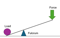

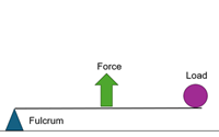
Forces at the translational ports act along the translational network direction. The fulcrum does not have to be stationary.
You can also model the lever rotational dynamics by enabling the rotational port R.

To define the coupling method of the rotational and translational motions, you can choose between a linearized small‑angle approximation or a full‑angle nonlinear geometry. Therefore, the block can model the lever in one of three ways:
Model 1 – No rotational port
Model 2 – Rotational port and linearized small‑angle approximation
Model 3 – Rotational port and full‑angle nonlinear geometry
You can use any of these models to represent a Class 1, Class 2, or Class 3 lever. The table lists the equations for each of these models.
Model 1 No Rotational Port | Model 2 Rotational Port and Linearized Approximation | Model 3 Rotational Port and Full‑Angle Geometry |
|---|---|---|
|
|
|
|
The block equations use these symbols:
r12 is the arm length between ports T1 and T2. This value corresponds to the Arm length T1-T2 parameter.
r23 is the arm length between ports T2 and T3. This value corresponds to the Arm length T2-T3 parameter.
lengthP12 is the orthogonal projection of the distance between ports T1 and T2 onto the translational network rail.
lengthP23 is the orthogonal projection of the distance between ports T2 and T3 onto the translational network rail.
lengthP13 is the orthogonal projection of the distance between ports T1 and T3 onto the translational network rail.
xT1, xT2, xT3 are the absolute positions on the translational network rail of ports T1, T2, and T3, respectively.
fT1, fT2, fT3 are the forces along the translational network rail at ports T1, T2, and T3, respectively.
τ is the torque of the lever acting on the rotational network at port R.
θ is the lever angle at port R.
ε is the positive rotation sign:
If the Positive angle parameter value is
Corresponds to positive projected length, ε = 1.If the Positive angle parameter value is
Corresponds to negative projected length, ε = –1.
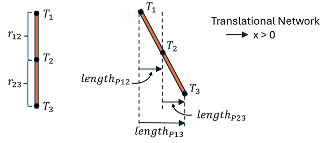
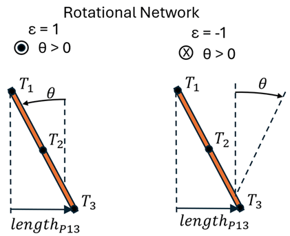
lengthP13 is the orthogonal projection of the distance between ports T1 and T3 onto the translational network rail. You can control it by specifying a high-priority target for the Projected length from T1 to T3 variable in the Initial Targets section in the block dialog box.
When the lever angle θ is 0 deg, the lever length is perpendicular to the translational network, and the Projected length from T1 to T3 is 0 m. Use the Positive angle parameter to change whether positive lever angles correspond to positive or negative projected lever lengths.
Variables
To set the priority and initial target values for the block variables prior to simulation, use the Initial Targets section in the block dialog box or Property Inspector. For more information, see Set Priority and Initial Target for Block Variables.
Nominal values provide a way to specify the expected magnitude of a variable in a model. Using system scaling based on nominal values increases the simulation robustness. Nominal values can come from different sources, one of which is the Nominal Values section in the block dialog box or Property Inspector. For more information, see Modify Nominal Values for a Block Variable.
Examples
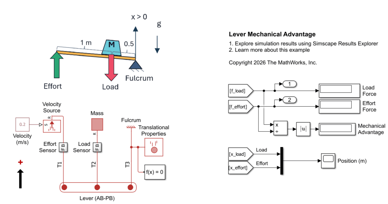
Lever Analysis
Use the Simscape™ Lever (AB-PB) block to model lever systems in the position-based translational and angle-based rotational domains. Two models demonstrate the torque balance and kinematic constraints of a lever. The first model computes mechanical advantage from force measurements. The second model predicts which end of a lever contacts a wall when two forces act on it.
Ports
Conserving
Parameters
Tips
To model rotational effects, such as pivot point damping or friction, or to model a torque source, enable the rotational port R. This port represents the rotation of the entire lever body. Connect all rotational effects related to the pivot support, external force source, or load to this rotational port, even though the block models these points using different translational ports.
If the lever operates at large angles, switch to full‑angle nonlinear geometry by clearing the Linearized small-angle approximation check box. In the linearized model with a rotational port, errors in the force and torque results scale with θ ^2, and errors in the projected lengths and angle results scale with θ ^3. For accurate results at greater angles, use the nonlinear model.
Models 1 and 2 produce an error when the Projected length from T1 to T3 variable exceeds the sum of Arm length T1-T2 and Arm length T2-T3 because that is physically impossible for a lever. If you receive this error, it means that the lever operates at a very large angle. In this case, you can switch to Model 3, which uses full‑angle nonlinear geometry.
When the block uses Model 3, it is more numerically sensitive than the other two models.
To avoid a solver error at angles of +/- 90 deg, connect a torque load to port R.
To maintain rotation past +/- 90 deg, connect an Inertia (AB) block to port R.
Extended Capabilities
Version History
Introduced in R2026b

