Add Reverb to Audio File Stored in SD Card of Arduino Hardware
This example shows how to add reverb to an audio file read using the SD Card File Read block from Simulink® Support Package for Arduino® Hardware. On deployment, the Simulink model reads audio from the SD card, adds the reverb effect to the audio, and then plays the processed audio through the headphones connected to the analog output pin of the hardware.
Required Hardware
Arduino MKR Zero or any other supported Arduino hardware
Headphones with 3.5mm audio jack (recommended)
USB cable
Prerequisite
Configure the Arduino network using Install Support for Arduino Hardware.
Simulink Model Description
Open the arduino_reverb Simulink model.

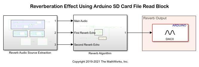
The model is divided into three areas based on the functionality of the blocks in each area:
Reverb Audio Source Extraction
Reverb Algorithm
Reverb Output
Reverb Audio Source Extraction: This subsystem reads the audio from the
sampleAudio_8kHz_8bit.wavfile stored in the SD card by using the SD Card File Read block. The audio file is set to repeat once the audio has finished playing. The audio is then passed to the Switch blocks in the Initial Reverb Delay Enabler for First Reverb Echo and Initial Reverb Delay Enabler for Second Reverb Echo areas. To generate reflection of sounds, the Switch blocks add initial delays of0.07seconds and0.140seconds to the audio signal. To generate the reverberation effect, the delayed audio signals are then added back to the original signal.
Reverb Algorithm: Adding the delayed and attenuated audio signals to the original signal saturates the analog output. This subsystem normalizes the output within the saturation limits and then lowers the rate of the normalized audio to 1 sample.
Reverb Output: The Analog Output block accepts the normalized audio and then plays the processed audio through the headphones connected to the DAC0 pin of the hardware.
Step 1: Connect Arduino Hardware for Reverb Effect
Before you start this example, we recommend you complete the Get Started with Arduino Hardware example.
1. Connect the micro end of the USB cable to the Arduino MKR Zero board and the regular end of the USB cable to the computer. Wait until the PWR LED on the hardware starts blinking.
2. Connect the headphone to the TRRS breakout shield as shown.
a. The Left and Right channels are on the TIP and RING1 of TRRS breakout. These channels are connected to the DAC0 pin of the hardware.
b. The Ground is on the RING2 of TRRS breakout. The Ground is connected to the GND pin of the hardware.

Step 2: Copy Audio File into SD Card
1. Insert the SD card in your computer.
2. Format the SD card to file allocation table 32 (FAT32) format. This step is required so that the example generates the desired output.
3. In the MATLAB® Command Window, execute the which command. This command displays the location of the sampleAudio_8kHz_8bit.wav file in your computer. Copy the sampleAudio_8kHz_8bit.wav file from its location and paste it to the root directory of the SD card.
which sampleAudio_8kHz_8bit.wav
4. Insert the SD card in your Arduino MKR Zero board. If you are using a board that does not have an inbuilt slot for the card, use an SD card shield.
Step 3: Configure Arduino Reverb Simulink Model
1. Open the arduino_reverb Simulink model.
2. In the Reverb Audio Source Extraction subsystem, the SD Card File Read block is configured to read audio from the sampleAudio_8kHz_8bit.wav file. If you want to use any other file that is already saved on your SD card, specify the name of that file in the File Name parameter and specify the properties of your audio file in the block parameters dialog box.
3. On the Modeling tab, select Model Settings.
4. Select the Hardware Implementation pane. From the Hardware board list, select the type of Arduino board that you are using.
5. From the SPI properties under Target hardware resources, set SD Card SPI CS pin to the Chip Select (CS) pin that your SD card shield uses for SPI communication with the connected SD card. Do not make any modifications if you are using Arduino MKR Zero board. As the MKR Zero board has an inbuilt SD card slot, the support package auto-populates the SD Card SPI SS pin parameter.
6. Click Apply. Click OK to close the dialog box.
Step 4: Deploy Simulink Model on Arduino Hardware
On the Hardware tab of the Simulink model, in the Mode section, select Run on board and then click Build, Deploy & Start. This action builds, downloads, and runs the model on the Arduino hardware. You can hear the reverb audio being played through the headphones connected to the analog output pin on the hardware. The audio continues to run even if the hardware is disconnected from the computer.
See Also
Other Things to Try
Open the arduino_audio_effects Simulink model.

Deploy the Simulink model on the Arduino hardware. This model implements the algorithm for adding echo and reverb, and pitch shifting the audio using MATLAB Function blocks. This model does not require SD card to process the audio.